Dipper door retarding mechanism

a technology of retarding mechanism and dipper door, which is applied in the direction of mechanical machines/dredgers, axially engaging brakes, mechanical apparatus, etc., can solve the problems of general lack of controllability of braking or retarding, uncontrolled swinging of the dipper door, structural damage to the door, etc., and achieves controllable braking amount, reduce shovel down time, and easy adjustment

Inactive Publication Date: 2011-10-06
PROJET INT
View PDF1 Cites 19 Cited by
  • Summary
  • Abstract
  • Description
  • Claims
  • Application Information

AI Technical Summary

Benefits of technology

[0011]By controlling the hydraulic pressure provided to the at least one piston, the amount of friction generated between the braking arms, the braking plates, and the braking disks, if any, can be easily adjusted, thereby allowing control over the amount of braking. Moreover, adjustment of the hydraulic pressure can be effected directly by an operator. The present invention therefore generally reduces shovel down time due to dipper door damages and also dramatically reduces the time typically required to adjust the retarding mechanism.

Problems solved by technology

Typically, failure to have the desired retarding effect on the dipper door will cause an uncontrolled swinging of the dipper door during the opening and closing operation thereof.
This uncontrollable swinging will cause repeated impacts between the dipper door and the dipper body, thereby generating excessive noise and subjecting the door to vibrations which will ultimately cause structural damages to the door, to the latching mechanism, and / or to the dipper body.
Though the aforementioned patents propose useful dipper brakes and retarding mechanisms, they generally lack controllability of the braking or retarding.

Method used


Image

  • Dipper door retarding mechanism
  • Dipper door retarding mechanism
  • Dipper door retarding mechanism

Examples


Embodiment Construction

[0024]A novel dipper door retarding mechanism will be described hereinafter. Although the invention is described in terms of specific illustrative embodiments, it is to be understood that the embodiments described herein are by way of example only and that the scope of the invention is not intended to be limited thereby.

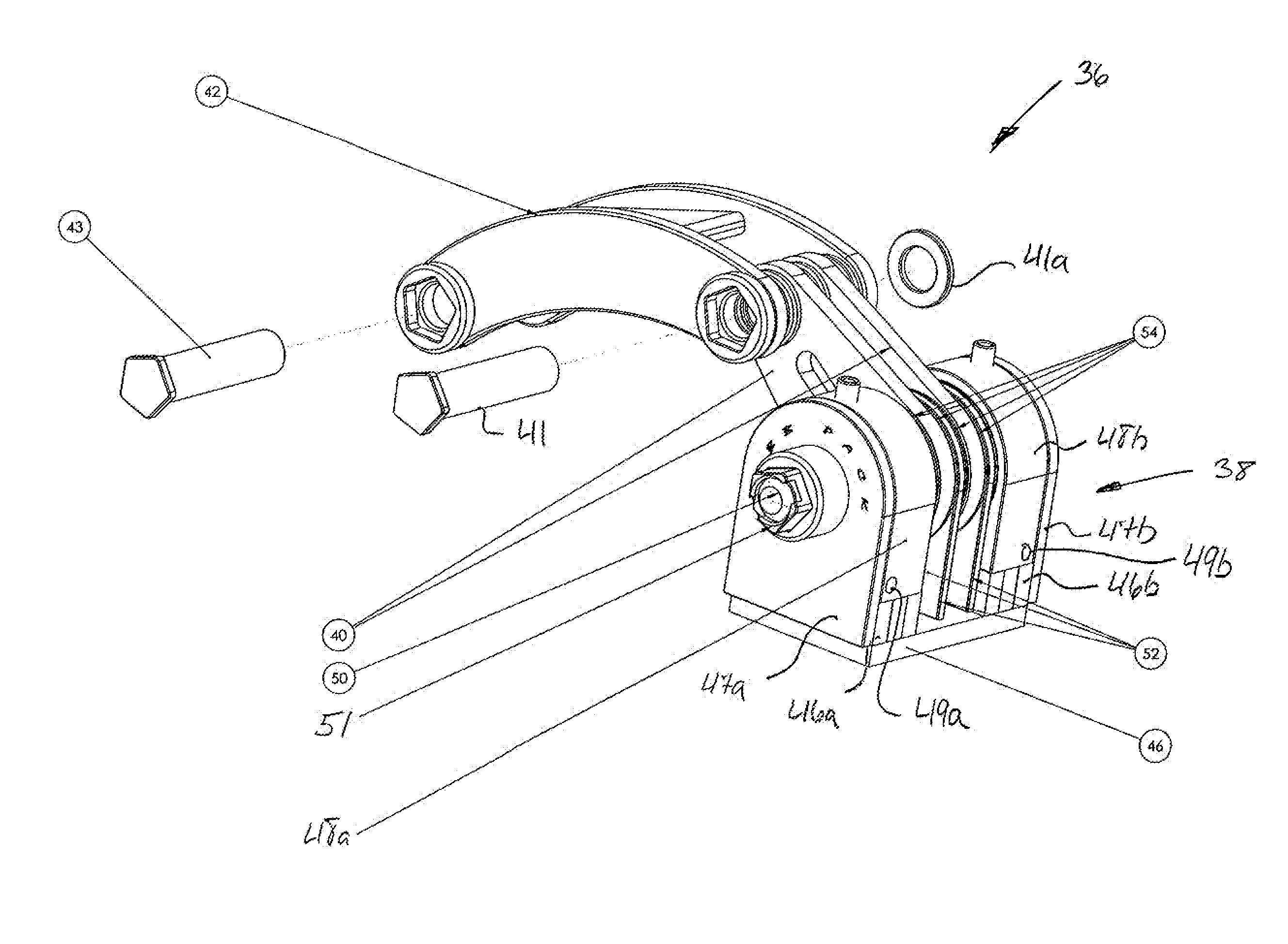
[0025]The present invention is preferably embodied in a retarding mechanism for continuously retarding the opening and closing, i.e. swinging, movements of the dipper door of the dipper of a mining shovel.

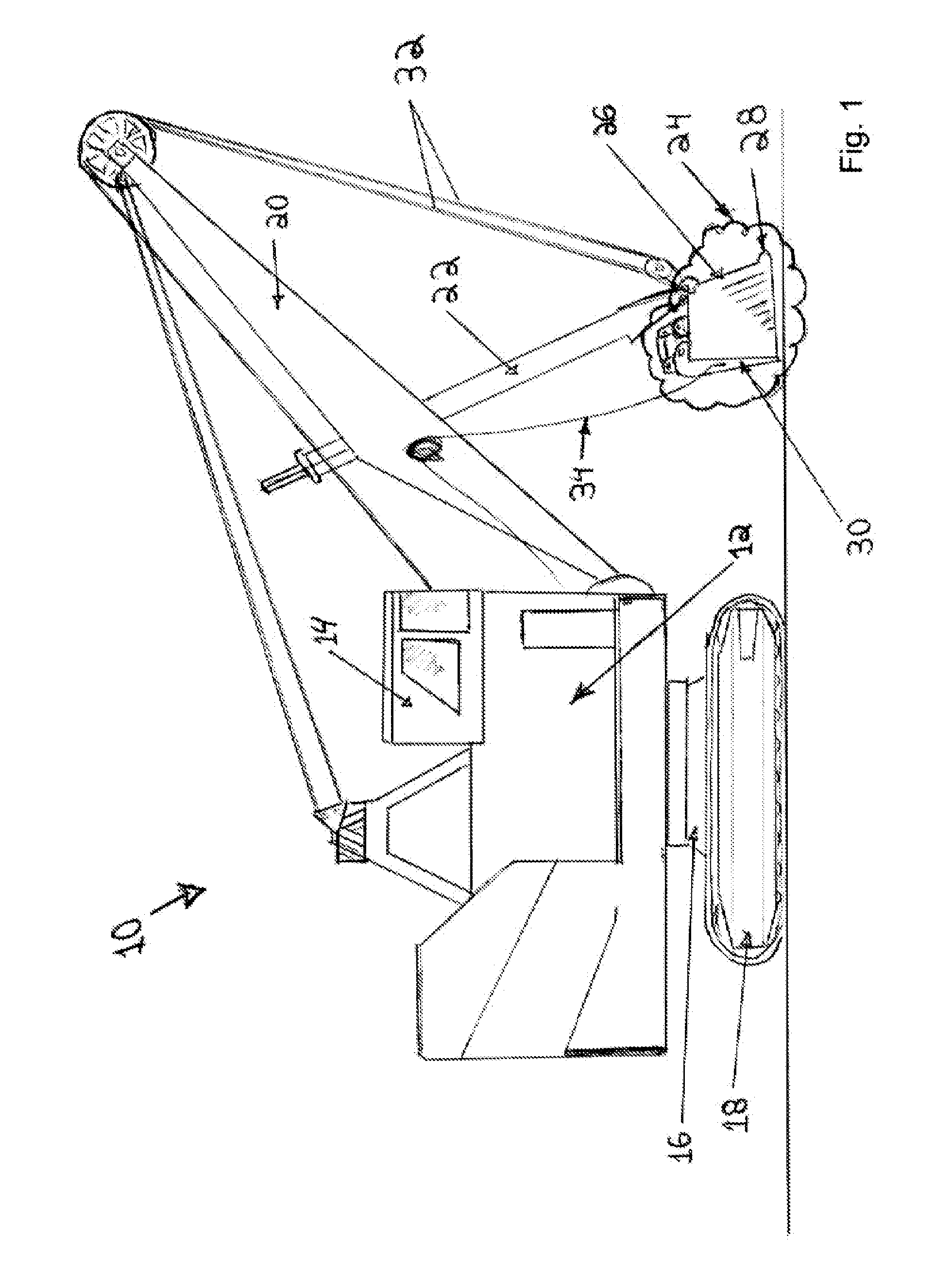
[0026]Referring first to FIG. 1, an exemplary electric-powered mining shovel 10 is depicted.

[0027]The mining shovel 10 has a machinery housing 12 and a control room 14 mounted on a chassis 16 supported by a pair of traction bands 18. Extending from the housing 12 is a boom 20 with an arm 22 pivotally mounted thereto. A dipper 24 is further mounted at the end of the arm 22.

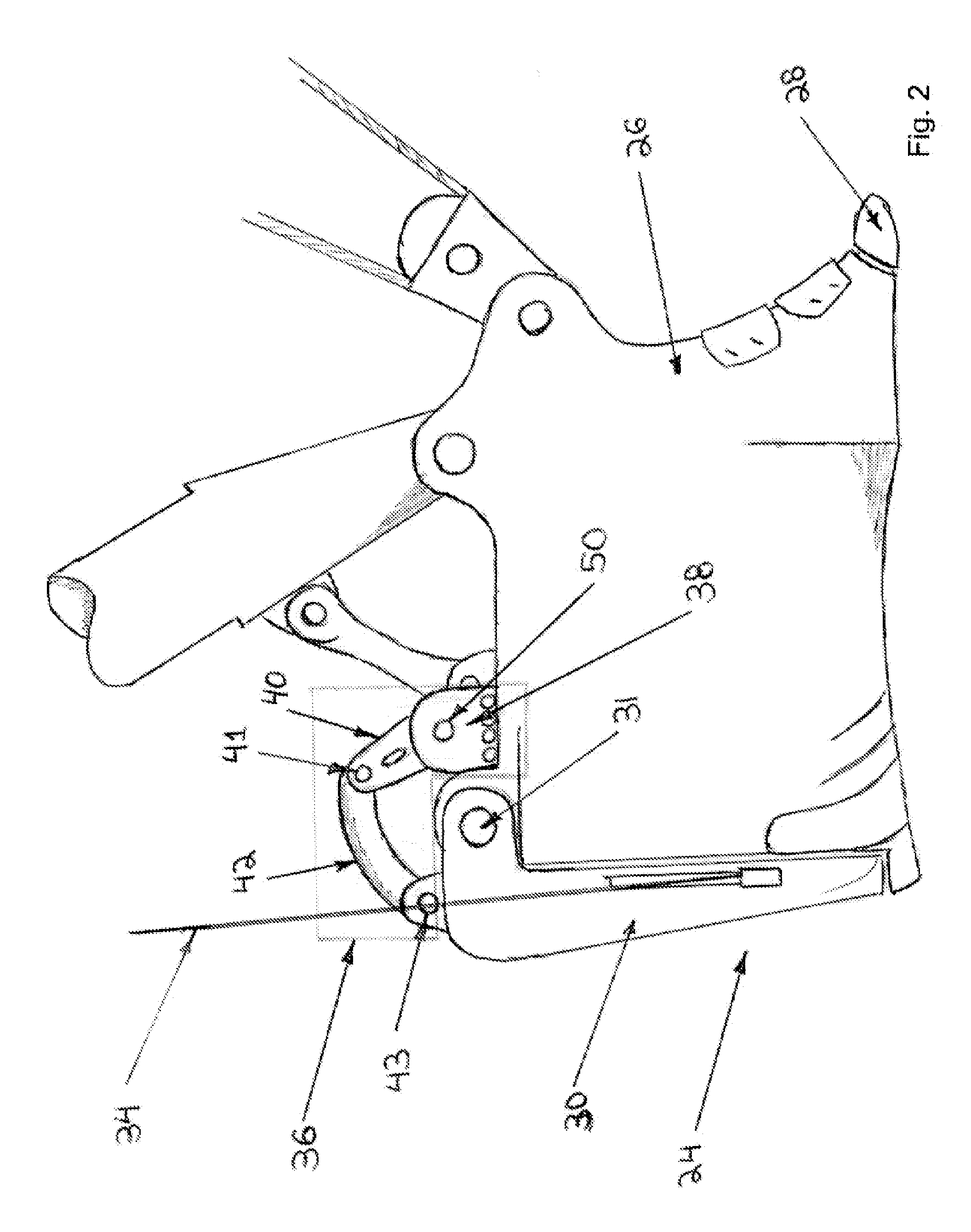
[0028]The dipper 24 has a hollow, generally rectangular body 26, forward-facing digging teeth 2...


PUM


Abstract

A retarding mechanism for continuously retarding the swinging movements of a dipper door is disclosed. The retarding mechanism comprises a hydraulic braking assembly mounted to the dipper bucket and operatively connected to the dipper door via at least one braking arm pivotally mounted within the braking assembly and at least one linking member pivotally mounted to the dipper door. The retarding mechanism continuously retards the opening and closing movements of the dipper door by controllably braking or slowing the at least one braking arm using the compressive action of at least one hydraulic piston mounted to the braking assembly.

Description

CROSS-REFERENCE TO RELATED APPLICATIONS[0001]The present patent application claims the benefits of priority of commonly assigned Canadian Patent Application No. 2,698,850, entitled “Dipper Door Retarding Mechanism” and filed at the Canadian Intellectual Property Office on Apr. 1, 2010, the content of which is incorporated herein by reference.FIELD OF THE INVENTION[0002]The present invention generally relates to the technical field of brakes, retarding mechanisms and snubbers for mining shovel dipper doors.BACKGROUND OF THE INVENTION[0003]Currently, to retard the swinging motion and to mitigate the “banging” problem of dipper doors, dipper manufacturers use door brakes and / or retarding mechanisms also known as “snubbers”. These brakes typically comprise a brake assembly installed on the dipper body and connected to the dipper door by a more or less complex linkage assembly.[0004]Examples of dipper door brakes can be found in the following U.S. Pat. Nos. 4,443,957; 4,517,756; 5,613,30...

Claims


Application Information

Patent Timeline
Patent Type & Authority Applications(United States)
IPC IPC(8): E02F3/40E02F9/00E02F3/407
CPCE02F3/304F16D2121/02F16D55/00E02F3/4075
Inventor DUBE, YANNICKLEVESQUE, ALEXANDRE
Owner PROJET INT
Why Eureka
Try Eureka