Solar central receiver

Inactive Publication Date: 2011-10-06
MITSUBISHI HEAVY IND LTD
View PDF3 Cites 37 Cited by
  • Summary
  • Abstract
  • Description
  • Claims
  • Application Information

AI Technical Summary

Benefits of technology

[0030]With the concentrated-solar-power-gas turbine power generation equipment of the present invention, the power generation efficiency is increased compared with the conventional configuration. Accordingly, the energy recovery rate can be improved, and the reliability can be improved.
[0031]The

Problems solved by technology

The amount of heat input differs between the heat transfer pipes 14 that are exposed to intense sunlight and the heat transfer pipes 14 that are exposed to diffuse sunlight, which leads to a problem in that a compressible working fluid passing through the heat transfer pipes 14 cannot be uniformly (evenly) heated.
Furthermor

Method used


Image

  • Solar central receiver
  • Solar central receiver
  • Solar central receiver

Examples


Example

[0065]Referring to FIGS. 1 to 4, a solar central receiver according to the first embodiment of the present invention will be described below.

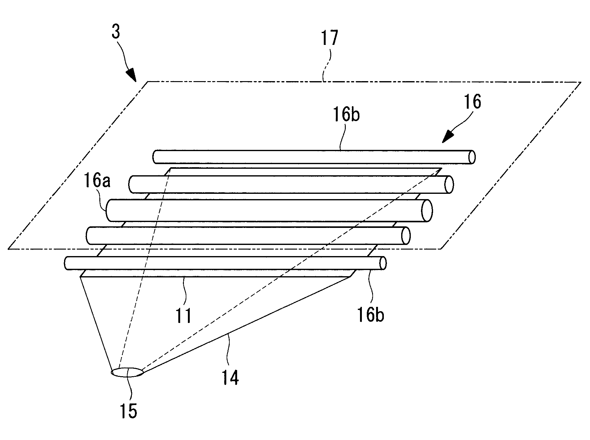
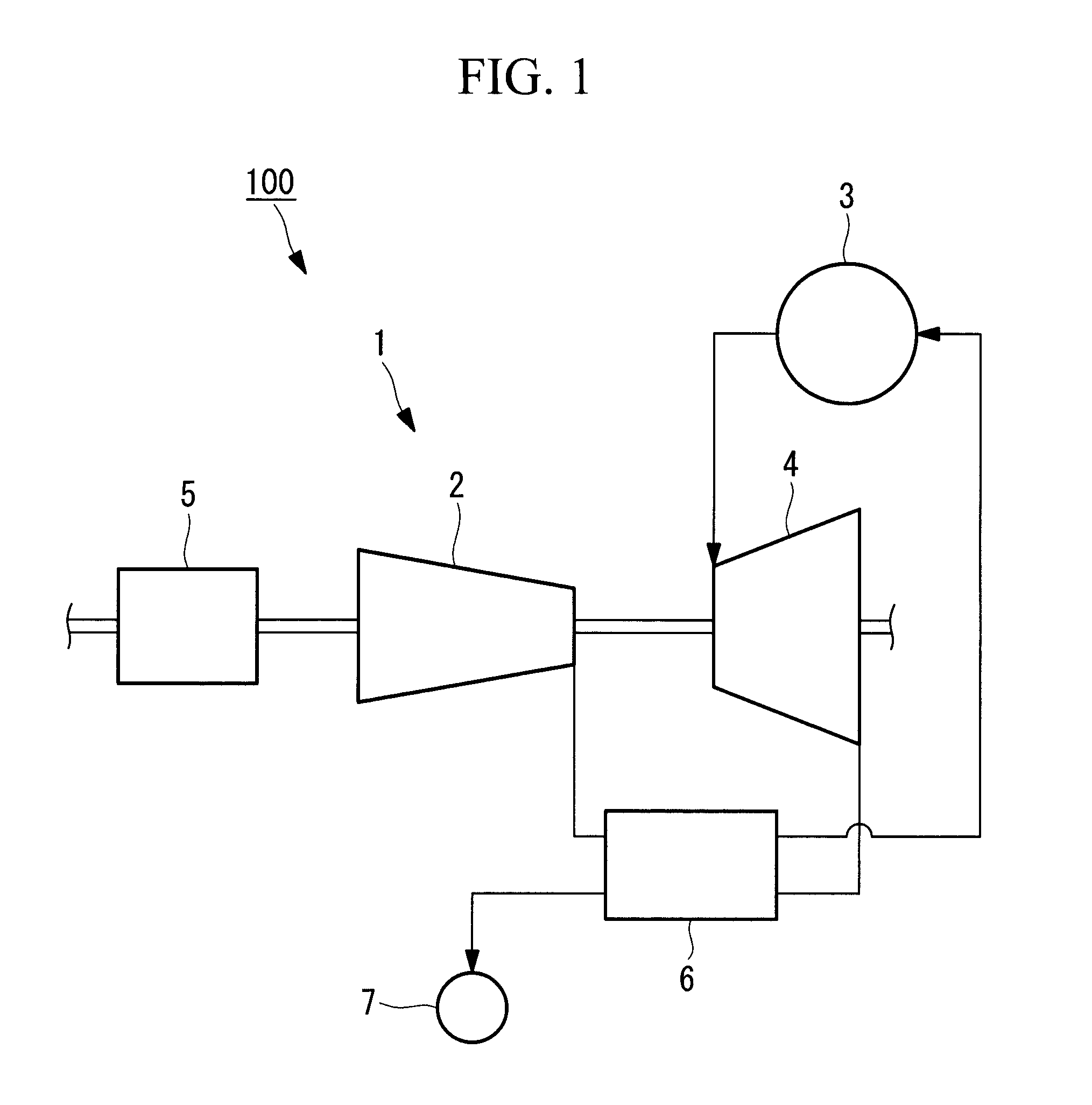
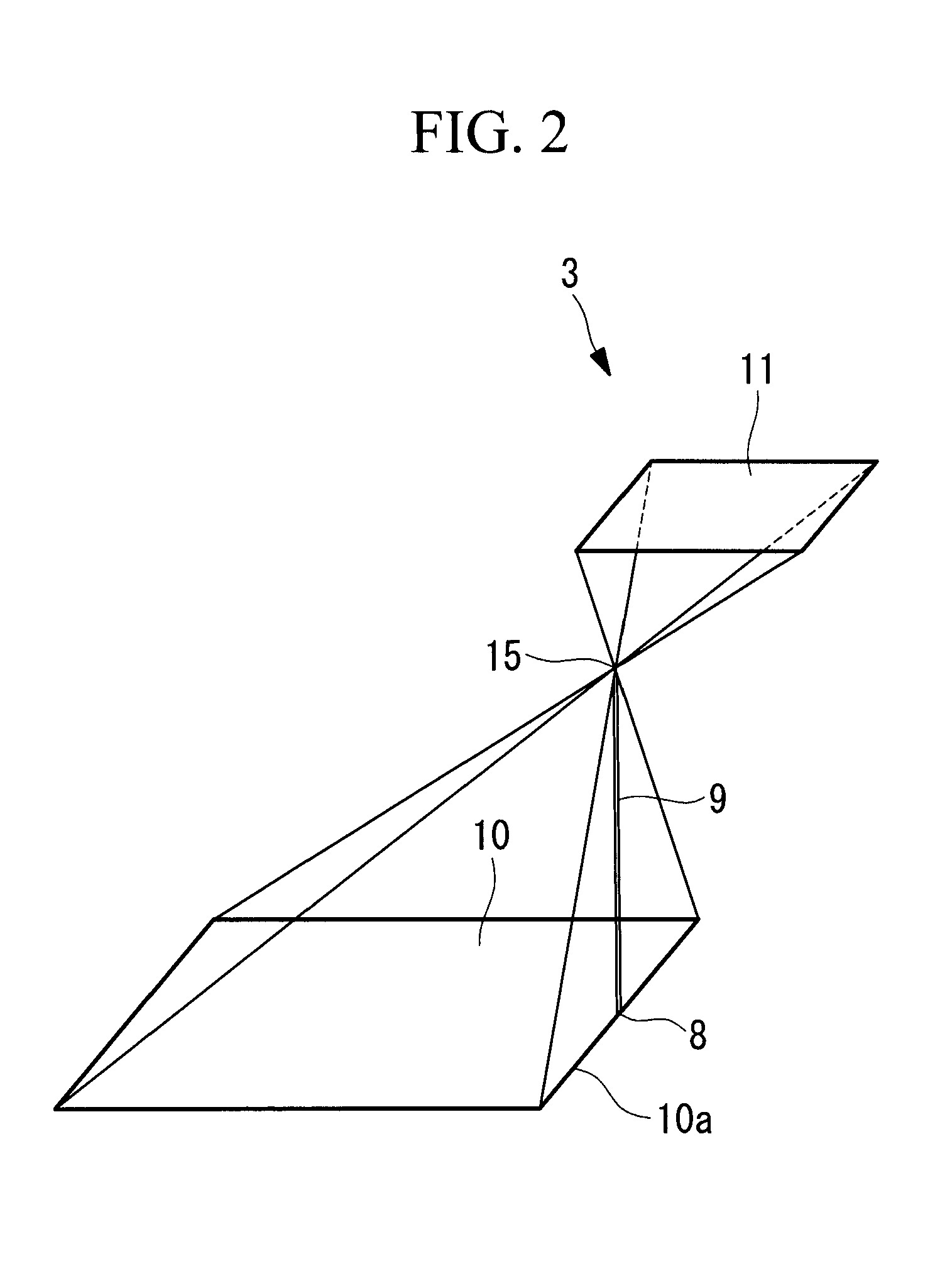
[0066]FIG. 1 is a schematic diagram of the configuration of a concentrated solar power gas turbine and a concentrated-solar-power-gas turbine power generation equipment having a solar central receiver according to this embodiment, FIG. 2 is a diagram for explaining the relationship between the solar central receiver according to this embodiment and a heliostat field on which heliostats for focusing sunlight onto this solar central receiver are disposed, FIG. 3 is a diagram for explaining the outline of the heliostats, and FIG. 4 is a schematic diagram of the configuration of the inside of the solar central receiver according to this embodiment.

[0067]As shown in FIG. 1, the concentrated solar power gas turbine 1 is an apparatus mainly composed of a compressor 2 that compresses a compressible working fluid (a working fluid such as air) to raise t...

Example

[0081]Referring to FIGS. 5 and 6, a solar central receiver according to a second embodiment of the present invention will be described.

[0082]FIG. 5 is a diagram for explaining the relationship between a solar central receiver according to this embodiment and a heliostat field on which heliostats for focusing sunlight onto this solar central receiver are disposed, and FIG. 6 is a schematic diagram of the configuration of the inside of the solar central receiver according to this embodiment.

[0083]As shown in FIG. 5, instead of the solar radiation receiving surface 11, a solar radiation receiving surface 22 is defined inside the solar central receiver 21 according to this embodiment, and, as shown in FIG. 6, instead of the heat transfer pipes 16, heat transfer pipes 23 are provided in the solar central receiver 21 according to this embodiment, which are the difference to the above-described first embodiment. Because the other components are the same as those in the above-described firs...

Example

[0093]Referring to FIG. 7, a solar central receiver according to a third embodiment of the present invention will be described.

[0094]FIG. 7 is a cross-sectional view showing the relevant part of the solar central receiver according to this embodiment.

[0095]As shown in FIG. 7 a solar central receiver 31 according to this embodiment is different from the above-described first embodiment in that heat transfer pipes 32 are provided, instead of the heat transfer pipes 16. Because the other components are the same as those in the above-described first embodiment, the descriptions of these components will be omitted here.

[0096]In this embodiment, a plurality of (for example, 500) heat transfer pipes (pipes) 32 having a circular external shape in the cross section thereof and the same outside diameters and inside diameters are arranged on the solar radiation receiving surface 11 (see FIG. 2 or 4) such that they are most dense at the center (the central portion) in the arrangement direction ...


PUM


Abstract

Heat transfer pipes uniformly heat a compressible working fluid passing there through with a simplified supporting structure and reduced manufacturing costs. A solar central receiver (3) on top of a tower on the ground includes heat transfer pipes (16) arranged in the south-north direction; and a casing (14) accommodating the pipes (16) and has a solar radiation inlet (15) through which sunlight reflected by heliostats on the ground is transmitted to the lower surface side of the pipes (16). The pipes (16) are at equal intervals on a solar radiation receiving surface (11) parallel to a heliostat field on which the collectors are, or inclined with respect to the heliostat field on which the collectors are, and the diameters of the pipes (16) are substantially inversely proportional to the shortest distance from the inlet (15) to the central axes of the respective pipes (16) in the longitudinal direction.

Description

TECHNICAL FIELD[0001]The present invention relates to a solar central receiver that heats and raises the temperature of a compressible working fluid passing through heat transfer pipes with the heat of sunlight.BACKGROUND ART[0002]There is known a solar central receiver (solar radiation collector) that heats and raises the temperature of a compressible working fluid passing through heat transfer pipes with the heat of sunlight, which is disclosed in, for example, PTL 1.CITATION LISTPatent Literature{PTL 1}[0003]Japanese Unexamined Patent Application, Publication No. Hei 2-52953DISCLOSURE OF INVENTION[0004]However, in a solar central receiver (heat receiver / accumulator) 1 disclosed in FIG. 5 of the above-mentioned PTL 1, a plurality of heat transfer pipes (heat transfer pipes having heat accumulating members) 14 are disposed in a cylindrical configuration around the central axis extending through the center of a solar radiation inlet (opening) 15. The amount of heat input differs bet...

Claims


Application Information

Patent Timeline
IPC IPC(8): F02C1/05F24J2/24F24J2/10F24S10/70F24S23/70
CPCF03G6/064Y02E10/46Y02E20/14Y02E10/41F24J2/10F24J2/24Y02E10/44F24J2/07F24S10/70F24S20/20F24S23/70Y02E10/40
Inventor AOYAMA, KUNIAKIINOUE, KEIKOBAYASHI, KAZUTA
Owner MITSUBISHI HEAVY IND LTD
Why Eureka
Try Eureka