
Fuel cell system

Inactive Publication Date: 2008-07-31
HONDA MOTOR CO LTD
View PDF5 Cites 4 Cited by
  • Summary
  • Abstract
  • Description
  • Claims
  • Application Information

AI Technical Summary

Benefits of technology

[0014]The present invention has been made based on the above findings, and an object of the present invention is to provide a fuel cell system which makes it possible to increase the power generation efficiency of a fuel cell.
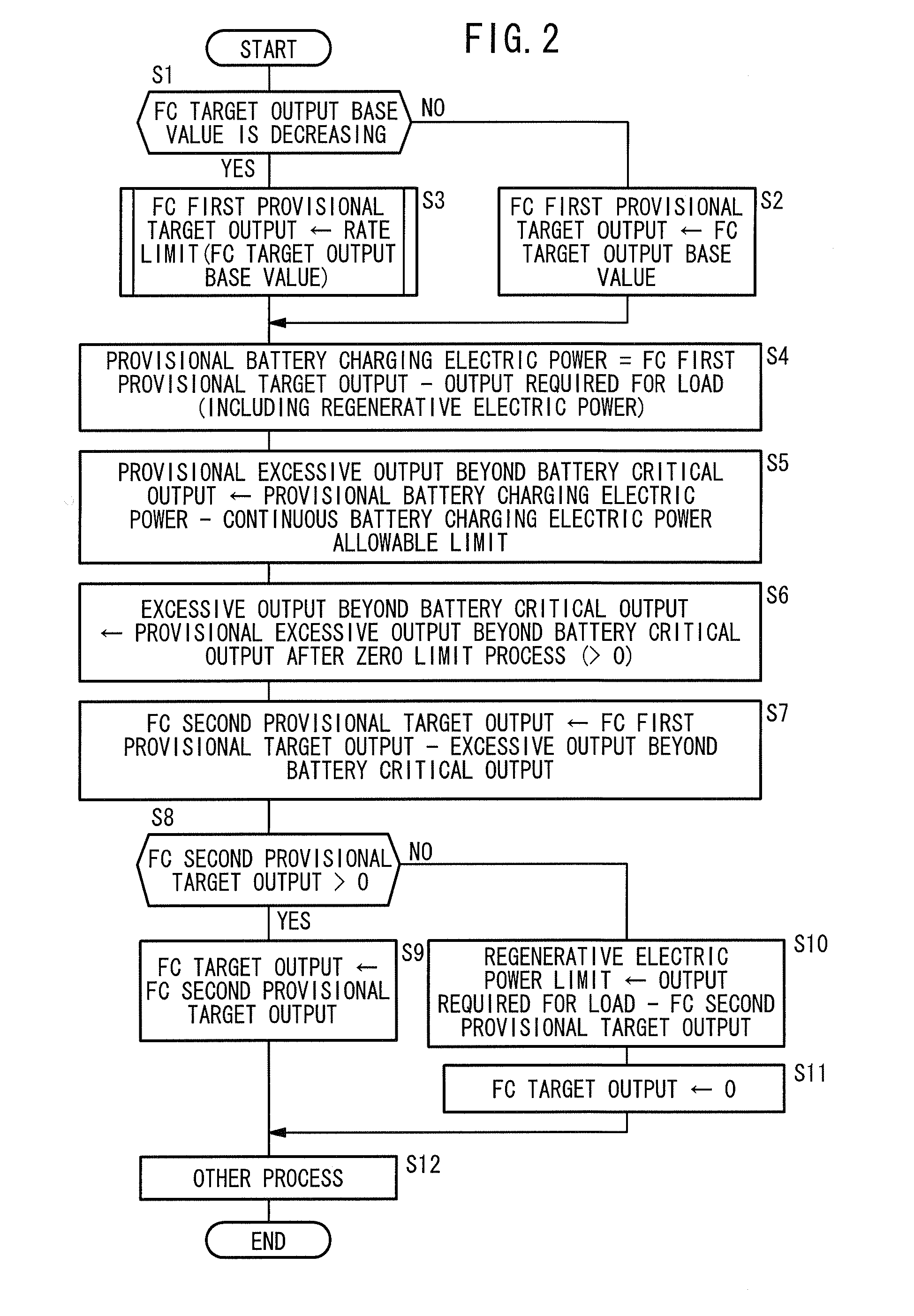
[0017]According to the invention having this feature, while the required output is decreasing, the target output of the fuel cell is decreased gradually to effectively utilize the high efficiency state of the fuel cell. Thus, it is possible to increase the average power generation efficiently.
[0019]According to the invention having this feature, it is possible to prevent the damage of the energy storage. Further, by charging the energy storage with the continuous charging electric power allowable limit, when the target output is increased the next time, further increase in the assisting electrical energy by the energy storage is achieved, and further improvement in the average efficiency is achieved.
[0023]In the invention having this feature, in the case where electric power generated by power generation of the fuel cell and regenerative electric power are supplied to the energy storage, if the total output exceeds the maximum output of the energy storage, firstly, electric power by power generation of the fuel cell is limited preferentially, and regenerative electric power is stored (collected) in the energy storage, and then, the regenerative electric power is limited. Thus, further improvement in the average power generation efficiency is achieved. In this case, since the limit adjustment means is provided, it is possible to prevent the energy storage from being damaged due to excessive charging electrical current.
[0024]In the present invention, while the required output of the fuel cell is decreasing, by gradually decreasing the target output of the fuel cell, the high efficiency state of the fuel cell during the decrease in the output is effectively utilized, and the efficiency is improved as a whole.

Problems solved by technology

During operation using the rated output, when the load is smaller than the rated output, the energy storage is charged by the excessive electric power.
However, in the conventional technique, no consideration is given for the change of efficiency at the time when the power generation output is increasing, and at the time when the power generation output is decreasing.

Method used


Image

  • Fuel cell system
  • Fuel cell system
  • Fuel cell system

Examples


Embodiment Construction

[0031]Hereinafter, embodiments of the present invention will be described with reference to the drawings.

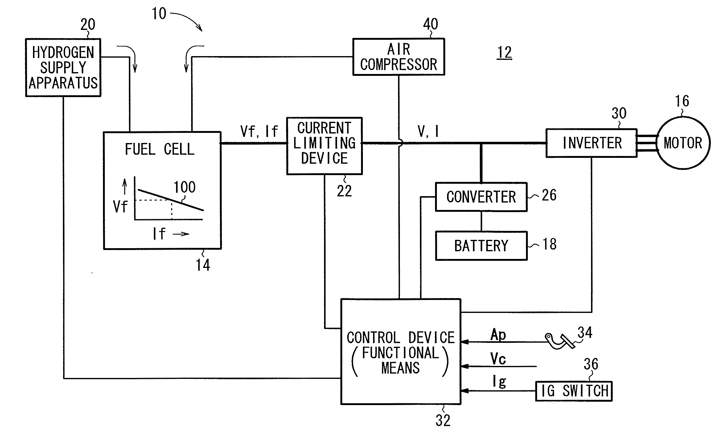
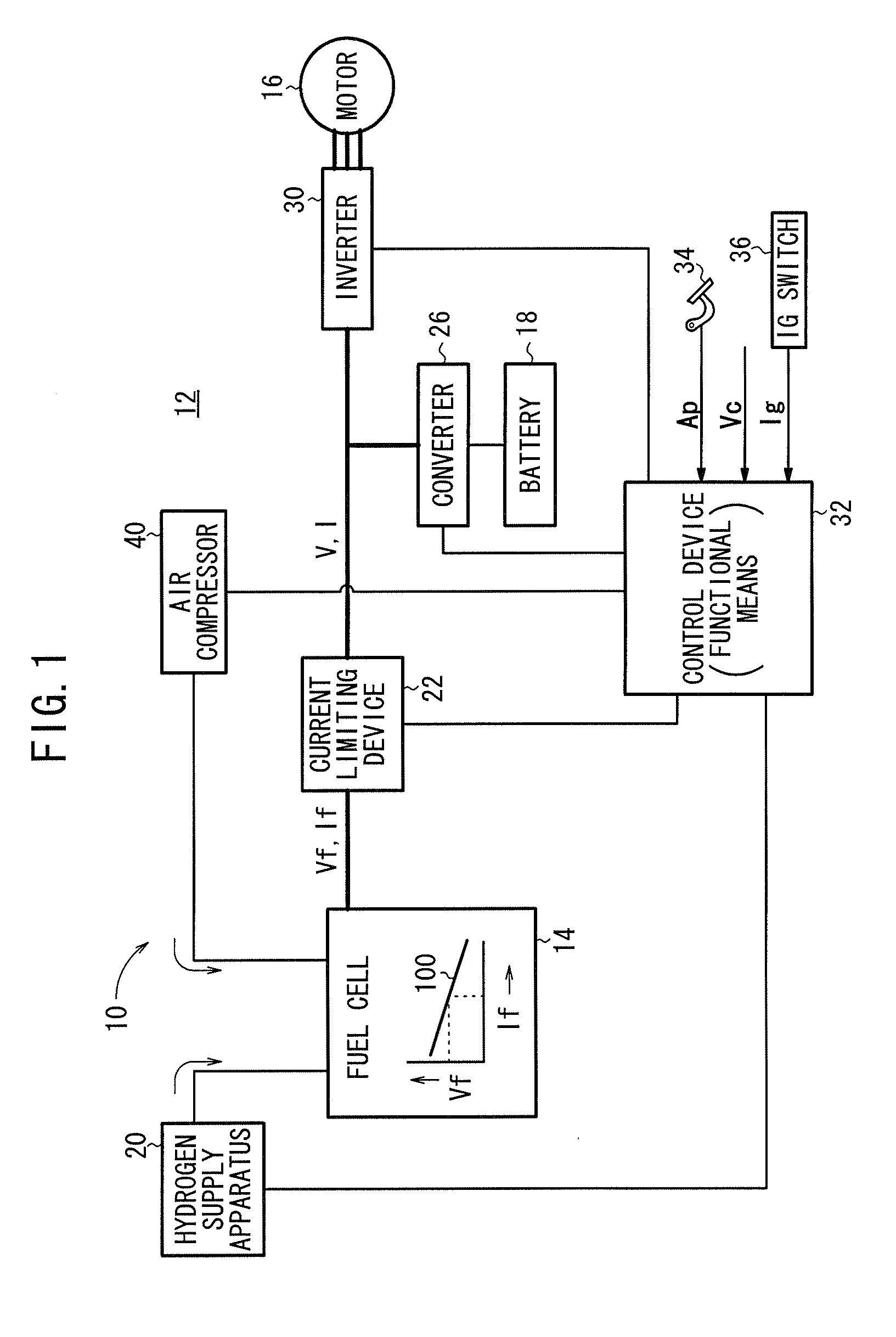
[0032]FIG. 1 is a diagram schematically showing structure of a fuel cell vehicle 12 including a fuel cell system 10 according to an embodiment of the present invention.

[0033]Basically, the fuel cell vehicle 12 includes a fuel cell 14, a travel motor (electric motor) 16, and a battery 18 as an energy storage charged by electric power generated by the fuel cell 14 and regenerative electric power supplied from the motor 16. The battery 18 also assists the output of the fuel cell 14. For example, the battery 18 is a lithium ion battery. Instead of the battery 18, a capacitor may be used as the energy storage.

[0034]The fuel cell 14 has stack structure formed by stacking a plurality of cells each including an anode, and a cathode, and a solid polymer electrolyte membrane interposed between the anode and the cathode.

[0035]A hydrogen supply apparatus 20 including a high pressure hydrogen...


PUM


Abstract

When the output of a fuel cell starts to decrease, in consideration of the increase in the power generation efficiency, an instruction for the output of the fuel cell undergoes a smoothing process to gradually decrease the output, and excessive electric power generated during a period in which the power generation efficiency is high is used for charging a battery. While the output of the fuel cell is increasing, the power generation efficiency of the fuel cell is low. Thus, assisting electrical energy from the battery is increased. In this manner, the power generation output when the power generation efficiency of the fuel cell is low is reduced from a high power generation output to a low power generation output to achieve improvement in the average power generation efficiency.

Description

BACKGROUND OF THE INVENTION[0001]1. Field of the Invention[0002]The present invention relates to a fuel cell system for controlling the efficiency of a fuel cell.[0003]2. Description of the Related Art[0004]For example, a polymer electrolyte fuel cell employs a membrane electrode assembly which includes an anode (fuel electrode) and a cathode (air electrode), and a polymer electrolyte membrane interposed between the electrodes. The electrolyte membrane is a polymer ion exchange membrane. The membrane electrode assembly is sandwiched between a pair of separators. A fuel gas flow field is formed between the anode and one of the separators, and an oxygen-containing gas flow field is formed between the cathode and the other of the separators. In use, normally, a predetermined numbers of the membrane electrode assemblies and separators are stacked together to form a fuel cell stack.[0005]In the fuel cell, a fuel gas such as a hydrogen-containing gas is supplied to the fuel gas flow field...

Claims


Application Information

Patent Timeline
IPC IPC(8): H01M8/04
CPCH01M8/04223H01M8/04559H01M8/04567H01M8/04589H01M8/04597Y02E60/50H01M8/0494H01M8/04955H01M16/006H01M2250/20Y02T90/32H01M8/0491Y02E60/10Y02T90/40H01M8/04228
Inventor SAEKI, HIBIKISHIRASAKA, TAKUYA
Owner HONDA MOTOR CO LTD
Learn More