Dynamic self-checking interlock monitoring system

a monitoring system and self-checking technology, applied in the field of fuel loading industry, can solve the problems of significant vapor being sent into the atmosphere, insufficient detection capability of current fuel loading monitoring systems, so as to prevent cheating

Active Publication Date: 2011-10-06
SCULLY SIGNAL CO
View PDF16 Cites 17 Cited by
  • Summary
  • Abstract
  • Description
  • Claims
  • Application Information

AI Technical Summary

Benefits of technology

[0011]Generally, an interlock monitoring system in accordance with an embodiment of the present invention includes a proximity sensor within a poppet valve hose type coupler to detect whether the poppet valve is opened or closed. The sensor consists of a proximity switch with dedicated electronics that prevents cheating by either shorting out or opening the contacts to the sensor. An insulated wire, for example Teflon®, travels through the vapor hose and out an exit port to a

Problems solved by technology

Many of the current fuel loading monitoring systems are inadequately equipped for detecting that vapor recovery is being properly implemented.
This method is effective, however, it is known to take a not insignificant amount of time after the product or liquid is loaded before vapor starts to flow in order to make a reading.
The issue is that significant vapor can be sent into the atmosphere if the hose is not connected during this grace period while fuel is being

Method used


Image

  • Dynamic self-checking interlock monitoring system
  • Dynamic self-checking interlock monitoring system
  • Dynamic self-checking interlock monitoring system

Examples


first embodiment

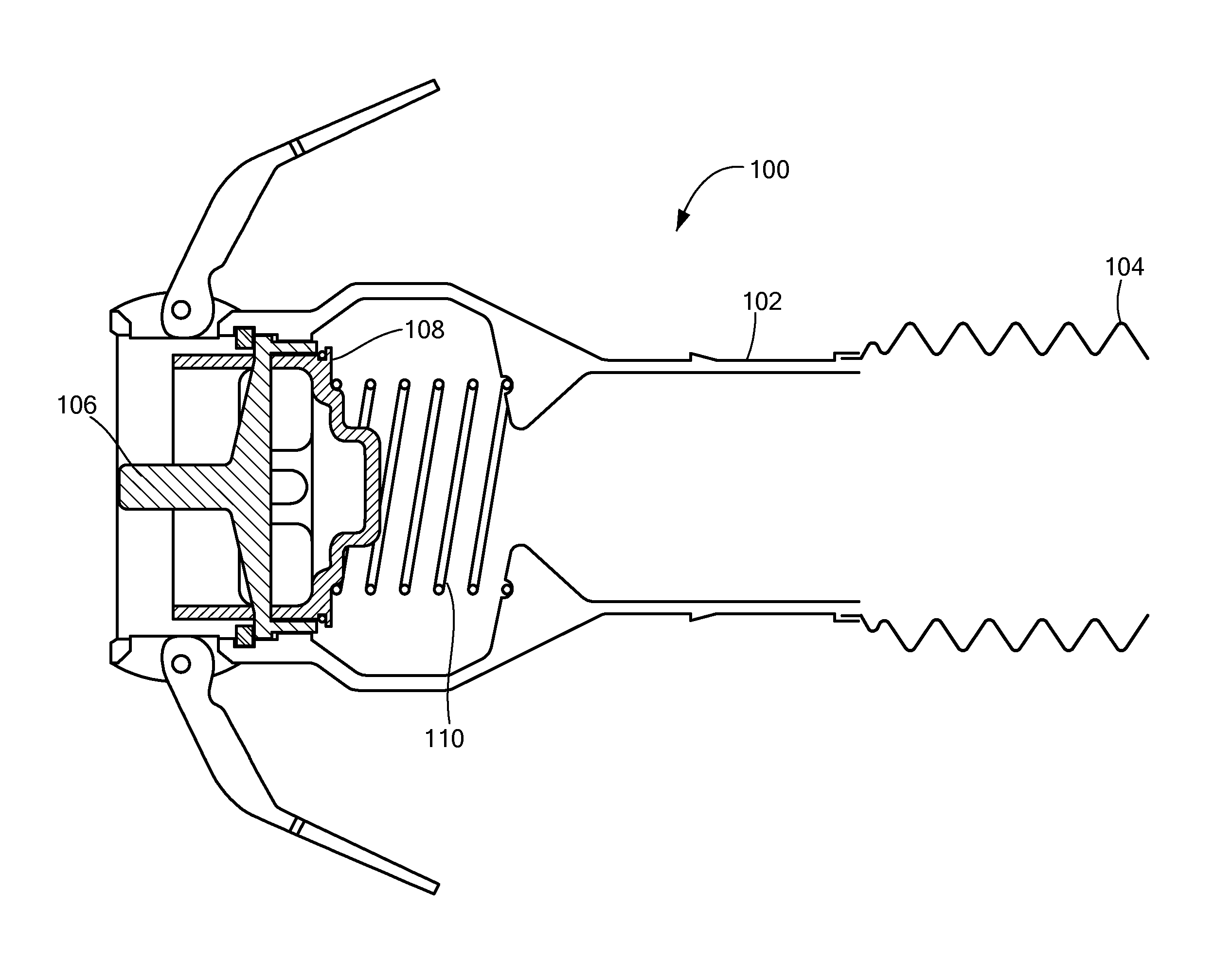
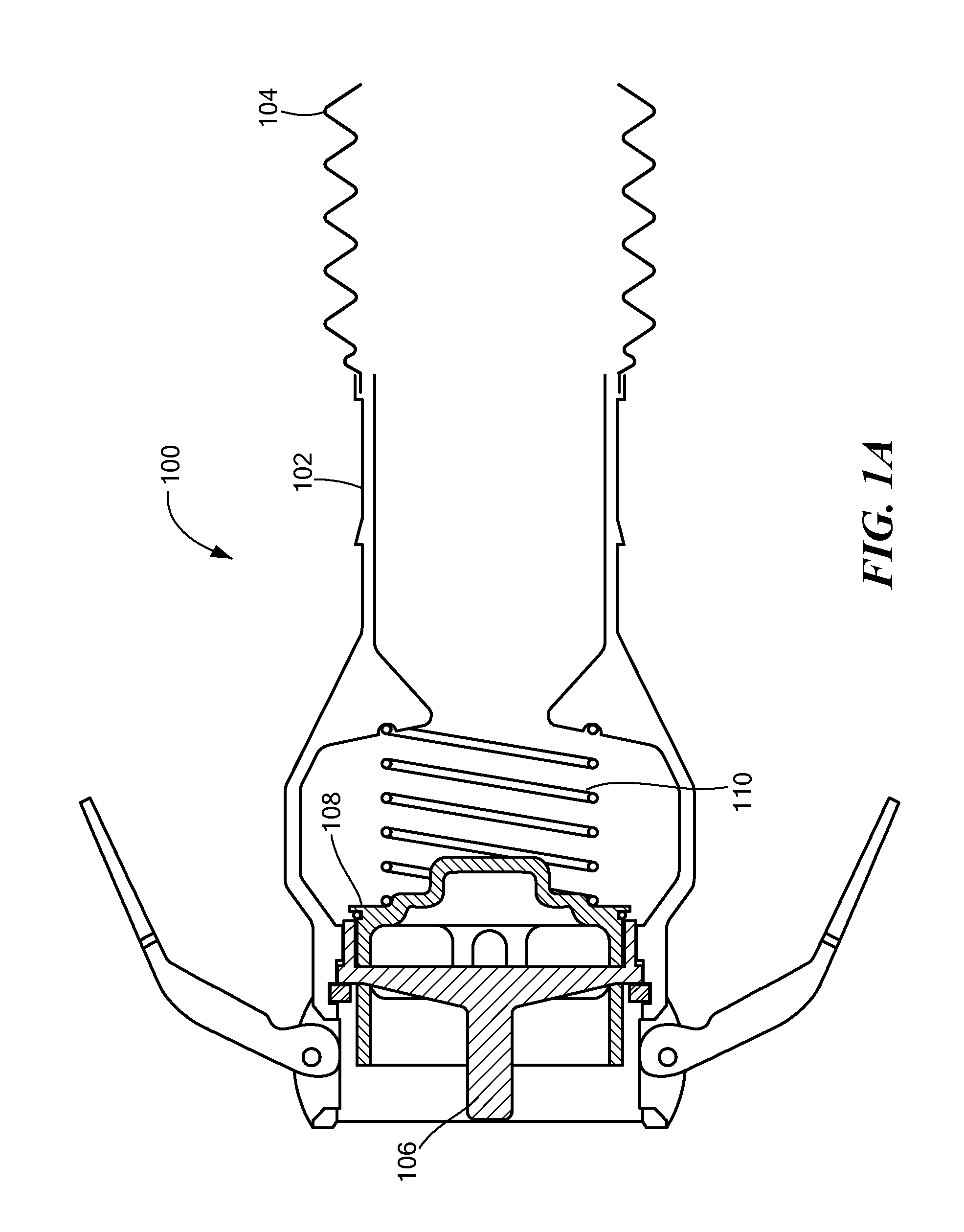
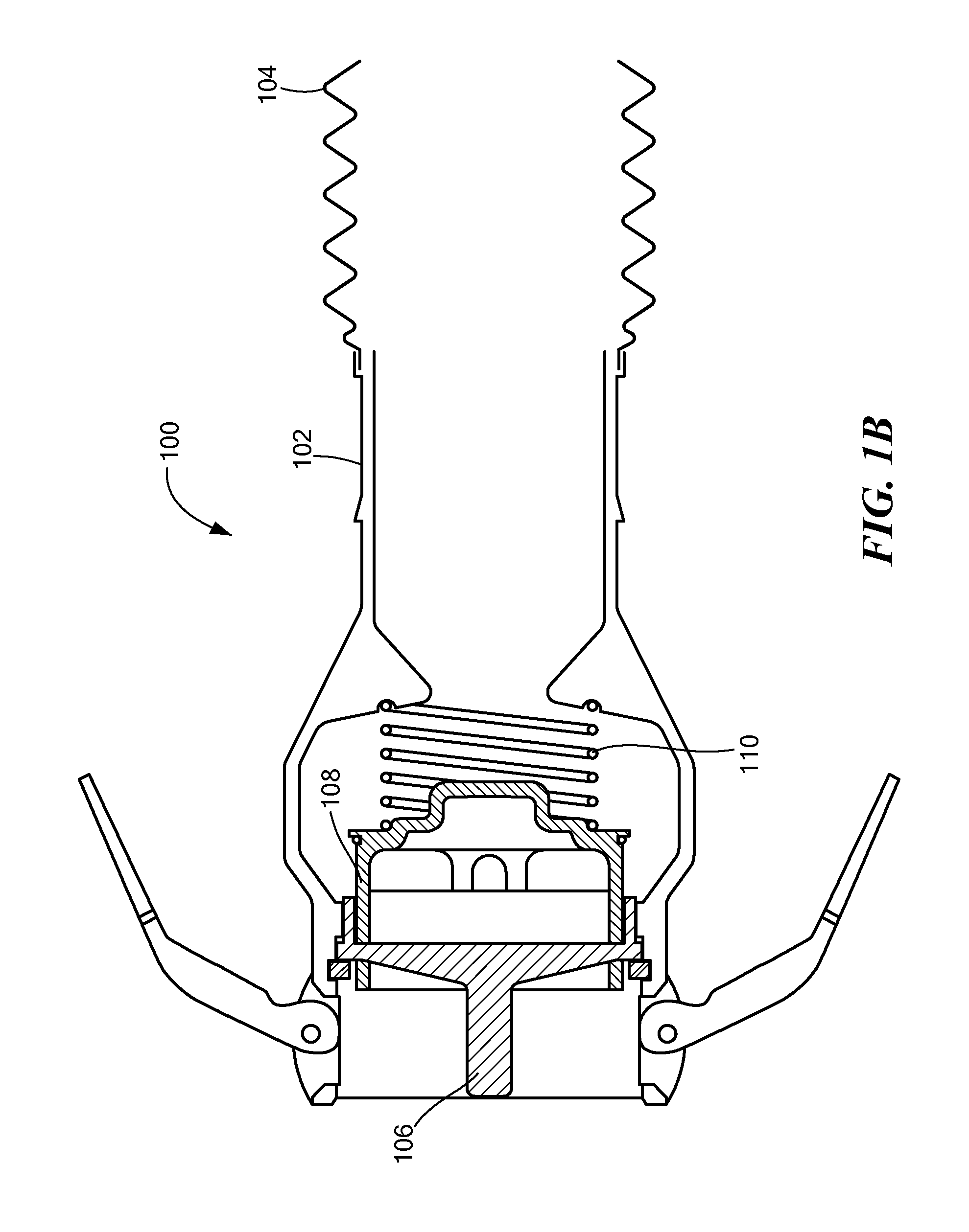
[0024]A vapor coupling poppet valve interlock 200 in accordance with the present invention is presented in FIGS. 2A and 2B. A magnet 202 is provided on the poppet 108 and its function will be described below. A mounting block 204 is provided inside the machined body 102 to hold a sensor 206 near the poppet 108. The sensor 206 is positioned to detect the magnet 202 when the poppet 108 is opened by operation of a fuel truck connecting to a fueling rack. An output of the sensor 206 is provided by an output wire 208, here shown with two conductors, running through the flexible hose and out through a vapor-tight exit port or gland, not shown. The wire 208 may be made from Teflon® or similar material so as to not be affected by the vapor and / or not cause a spark or otherwise create a possibly dangerous condition.

[0025]Alternatively, the sensor 206 may be provided with wireless capabilities in order to communicate with the controller. Of course, the signal strength and characteristics woul...

second embodiment

[0032]A vapor coupling poppet valve interlock assembly 400 in accordance with the present invention is presented in FIGS. 4A and 4B. Many components of this assembly 400 are the same as that shown in the embodiment presented in FIGS. 2A and 2B. A ferrous metal proximity sensor 402, such as the N-Series switch from Magnasphere Corp. of Waukesha, Wisc., is provided in the pin 106. The ferrous sensor 402 comes in either a normally-open or normally-closed configuration and will switch states when in proximity with a ferrous metal such as the pin on the coupling mechanism of the truck. The sensor 402 is coupled, via a wire 404, to a sensor 406 that will be described in more detail below.

[0033]In operation, similar to the embodiment described above, when the vapor coupling assembly 400 is attached to the truck's connector, the poppet 108 and magnet 202 will be urged toward the sensor 406. The ferrous metal proximity sensor 402 will change state and that change in state is coupled to the s...


PUM

PropertyMeasurementUnit
Flow rateaaaaaaaaaa
Distanceaaaaaaaaaa
Proximity effectaaaaaaaaaa

Abstract

An interlock monitoring system includes a magnetic proximity sensor within a poppet valve type coupler to detect whether the poppet valve is opened or closed. An open poppet valve indicates a proper connection. The sensor consists of dedicated electronics that prevent cheating, or bypassing, by either shorting out or opening the contacts to the sensor. In addition, a ferrous metal proximity switch is used to provide a redundant confirmation of proper connection of the coupler. The ferrous magnetic proximity switch will indicate whether or not the coupler is actually in contact with an appropriate connection. Each of the magnetic proximity sensor and the ferrous magnetic proximity switch must indicate a respective proper condition in order to determine a valid interlock condition.

Description

CROSS REFERENCE TO RELATED APPLICATIONS[0001]This application is a non-provisional application claiming priority from U.S. Provisional Patent Application No. 61 / 319,120 filed Mar. 30, 2010 entitled “Dynamic Self-Checking Interlock Monitoring System.”BACKGROUND OF THE INVENTION[0002]In the fuel loading industry where a fuel truck is being loaded with a liquid or fuel that is often flammable, in order to meet mandated safety requirements, several parameters of the fuel transfer process are routinely monitored for compliance with loading operations standards. These parameters include, commonly, assuring that a static ground is present in order to prevent sparking and monitoring tank capacity in order to avoid an overfill condition and possible fuel spill.[0003]In addition, vapor recovery during the filling process, in order to meet environmental and safety guidelines, is becoming increasingly important. Many of the current fuel loading monitoring systems are inadequately equipped for d...

Claims


Application Information

Patent Timeline
IPC IPC(8): B23P11/00F16K37/00
CPCB67D7/54Y10T137/0318Y10T137/0402Y10T137/8175Y10T137/8225Y10T137/8242
Inventor TROTTIER, ROBERT R.
Owner SCULLY SIGNAL CO
Why Eureka
Try Eureka