Cooling disc for bundles of current carrying cables

a current carrying cable and cooling disc technology, applied in the direction of cables, insulated conductors, conductors, etc., can solve the problems of reducing the current carrying capability of the cable, preventing efficient heat dissipation per unit time, and dissipating heat of current carrying cables, so as to achieve efficient spatial heat distribution and effectively cool the cable

Inactive Publication Date: 2011-10-06
GOOGLE LLC
View PDF2 Cites 8 Cited by
  • Summary
  • Abstract
  • Description
  • Claims
  • Application Information

AI Technical Summary

Benefits of technology

[0007]In accordance with aspects of the invention, one or more cooling discs are used to secure multiple current carrying cables while spreading the cables out in an organized manner. The cooling discs provide an efficient spatial distribution of heat so that the amount of power dissipated over time is distributed over a larger volume, effectively cooling the cables. Thus, it is not necessary to derate the cables.

Problems solved by technology

Unfortunately, current carrying cables dissipate heat.
Bundling such cables together prevents efficient heat dissipation per unit time, as it keeps more heat within the core of the bundle.
This may reduce the current carrying capability of the cables.
It may also reduce the useful life of a given cable and may cause a fire hazard.
However, this increases the size and expense of the cables.

Method used


Image

  • Cooling disc for bundles of current carrying cables
  • Cooling disc for bundles of current carrying cables
  • Cooling disc for bundles of current carrying cables

Examples


Embodiment Construction

[0021]Aspects, features and advantages of the invention will be appreciated when considered with reference to the following description of preferred embodiments and accompanying figures. The same reference numbers in different drawings may identify the same or similar elements. Furthermore, the following description is not limiting; the scope of the invention is defined by the appended claims and equivalents.

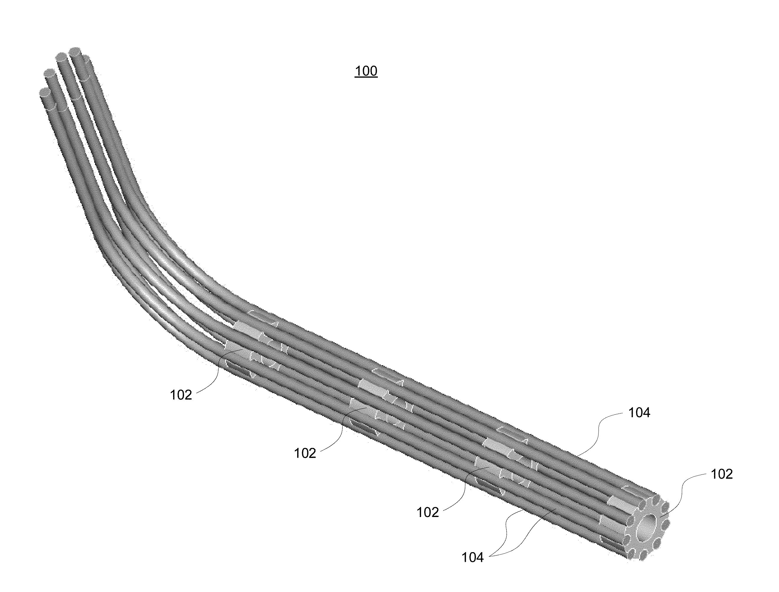
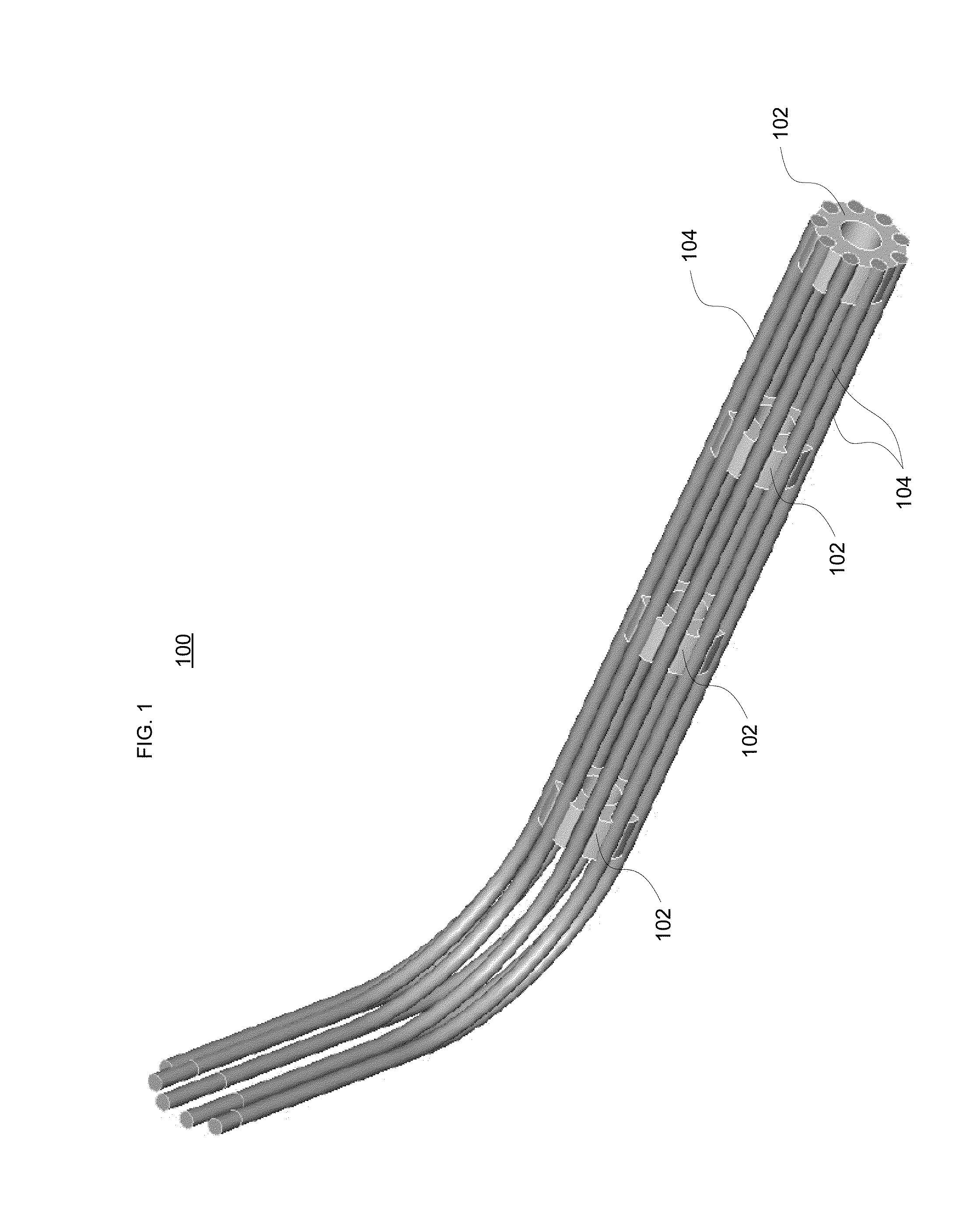
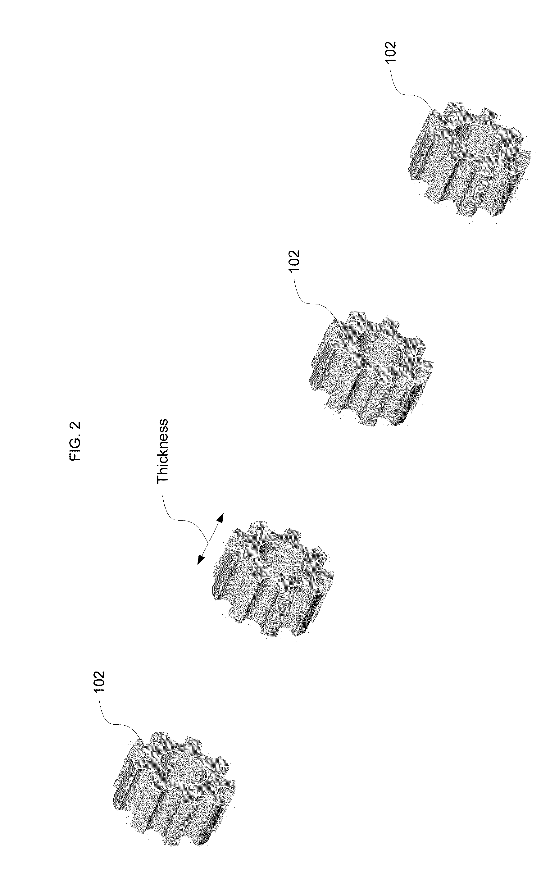
[0022]As noted above, current carrying cables may dissipate significant heat per unit time. This is a function of the amount of current which is carried by the cables, the thickness of the conducting material, the insulation and the cooling and ventilation available. By way of example, the current may be 30 Amps per cable or more, depending upon the application.

[0023]FIG. 7 illustrates an exemplary conventional example of a bundle 10 of current carrying cables 1-9. Cable 5, being in the center of the bundle, will be the warmest because it is surrounded by the other cables. The f...


PUM

PropertyMeasurementUnit
thicknessaaaaaaaaaa
thicknessaaaaaaaaaa
temperatureaaaaaaaaaa

Abstract

Aspects of the invention pertain to cooling bundles of power distribution cables or other current carrying cables. Such cables give off heat, especially when carrying high current loads. One or more cooling members are used to secure multiple cables. The cables may be placed about a generally circular shaped member which has a central opening. Receptacles are placed along an outer perimeter of the cooling member to secure the cables. The thickness of each cooling member may vary. When multiple cooling members are used, they may be spaced at least 6 inches apart. The cooling members may be fabricated from a nonconductive material such as PVC.

Description

BACKGROUND OF THE INVENTION[0001]1. Field of the Invention[0002]Aspects of the invention relate generally to heat dissipation in power distribution systems. More particularly, aspects provide cooling of current carrying cable bundles.[0003]2. Description of Related Art[0004]Power distribution systems are used in many different applications such as large scale computer systems.[0005]Such systems often use multiple cables, and each cable may support a high current. Often, two or more current carrying cables are bundled together using tie-wraps (cable ties) or other equipment. Bundling allows for convenient handling of the cables and gives the appearance of an orderly arrangement.[0006]Unfortunately, current carrying cables dissipate heat. Bundling such cables together prevents efficient heat dissipation per unit time, as it keeps more heat within the core of the bundle. This may reduce the current carrying capability of the cables. It may also reduce the useful life of a given cable a...

Claims


Application Information

Patent Timeline
Patent Type & Authority Applications(United States)
IPC IPC(8): H01B7/00
CPCH02G3/32H02G3/03
Inventor LIPIANSKY, EDUARDO M.KAM, PASCAL C.
Owner GOOGLE LLC
Why Eureka
Try Eureka