Snowmobile Frame

a frame and snowmobile technology, applied in the field of snowmobile frames, can solve the problems of plastic deformation of the frame, less than perfect alignment of transmission components, and insufficient repair of the vehicl

Inactive Publication Date: 2011-10-06
BOMBARDIER RECREATIONAL PROD INC
View PDF2 Cites 13 Cited by
  • Summary
  • Abstract
  • Description
  • Claims
  • Application Information

AI Technical Summary

Benefits of technology

[0010]It is also an object of the present invention to provide a snowmobile frame that maintains alignment between the engine cradle and the tunnel when experiencing an impact severe enough to damage the frame.
[0011]It is also an object of the present invention to provide a snowmobile frame that resists plastic deformation of the tunnel when experiencing an impact severe enough to damage the frame.

Problems solved by technology

However, it is possible for the impact to be severe enough to cause plastic deformation of the frame 10.
Attempting to repair the snowmobile by restoring the shape of the existing frame 10 can result in a less than perfect alignment of transmission components, because the bends cannot always be completely removed.
In these cases, it is impossible to adequately repair the vehicle without replacing the entire frame 10, resulting in high repair costs.

Method used


Image

  • Snowmobile Frame
  • Snowmobile Frame
  • Snowmobile Frame

Examples


Embodiment Construction

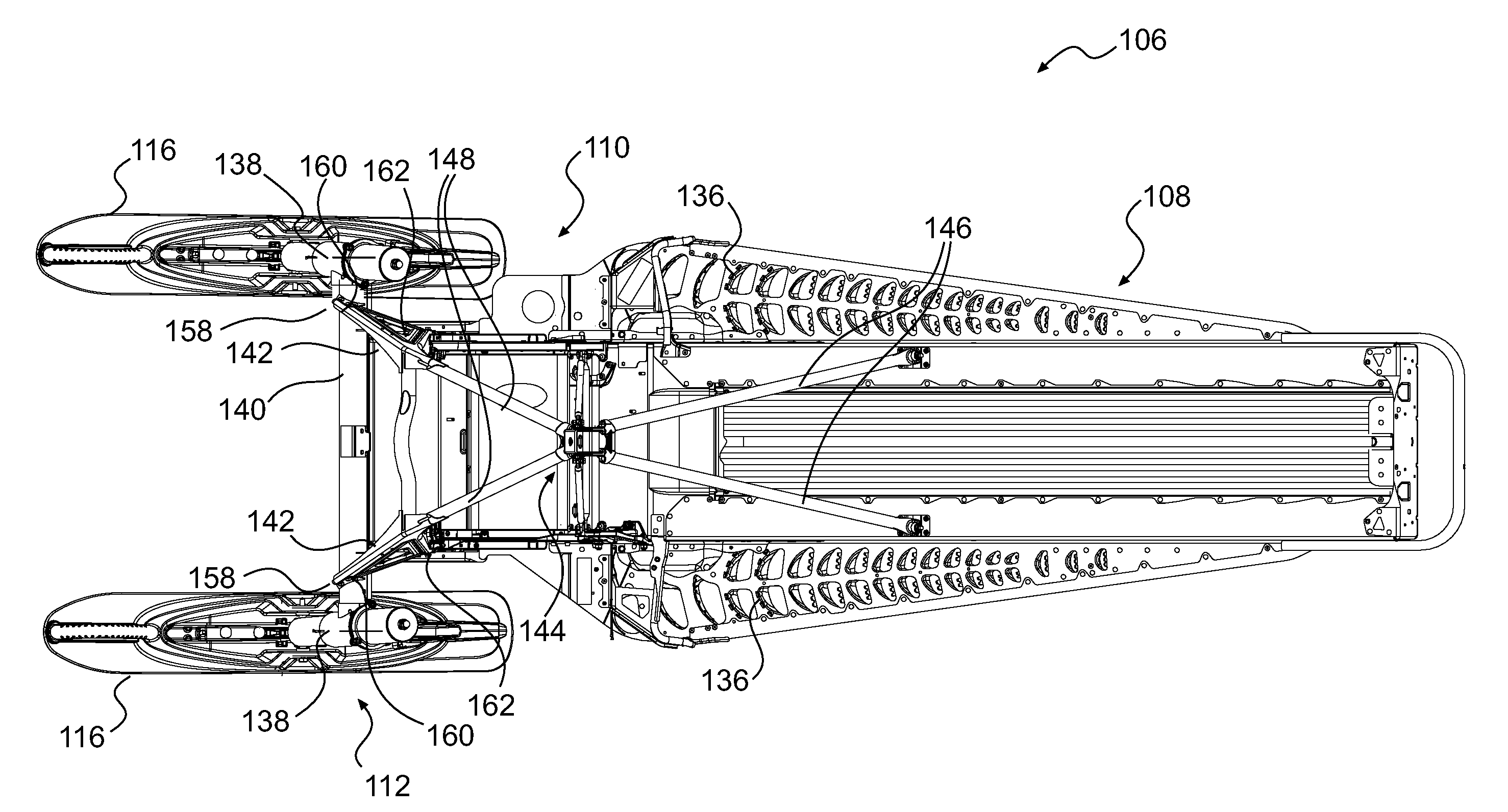
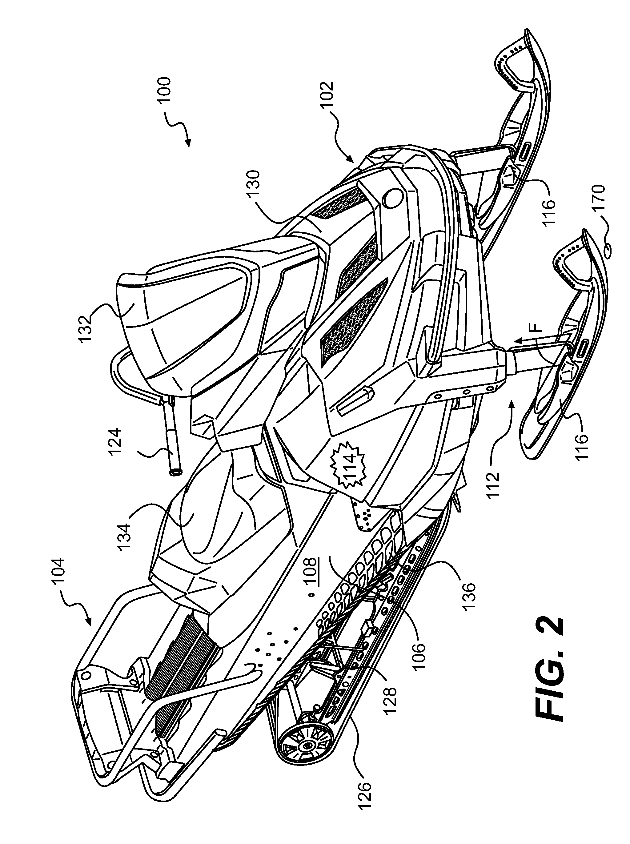
[0045]As shown in FIG. 2, a snowmobile 100 according to the present invention includes a forward portion 102 and a rearward portion 104 which are defined consistently with a forward travel direction of the vehicle. As best seen in FIGS. 3 and 4, the snowmobile 100 includes a frame (also known as a chassis) 106 which includes a rear tunnel 108, an engine cradle 110 (seen in FIG. 3) attached to a forward portion of the tunnel 108 and extending forwardly therefrom, and a front suspension assembly 112 disposed forwardly of the engine cradle 110 and attached thereto in a manner that will be discussed below in further detail. An engine 114 (shown schematically) is carried by the engine cradle portion 110 of the frame 106 which forms part of an engine compartment. The engine 114 is oriented such that the crankshaft (not shown) is transverse to the normal direction of travel of the snowmobile 100. Two skis 116 are positioned at the forward portion 102 of the snowmobile 100 and are attached ...


PUM


Abstract

A snowmobile frame (106) is described, with a tunnel (108) having an inverted U-shape. An engine cradle (110) is attached to a forward portion of the tunnel. A suspension assembly (112) is disposed forwardly of the engine cradle. At least one support member (142) supports the suspension assembly on the engine cradle. The at least one support member forms a crumple zone between the suspension assembly and the engine cradle. The at least one support member resists plastic deformation in response to the first predetermined force exerted on the suspension assembly. The at least one support member undergoes plastic deformation in response to a second predetermined force being exerted on the suspension assembly. The second predetermined force is greater in magnitude than the first predetermined force. The tunnel resists plastic deformation in response to the second predetermined force.

Description

CROSS-REFERENCE[0001]The present application is the United States National Stage of PCT / US2008 / 085059, filed Nov. 28, 2008, entitled ‘Snowmobile Frame’, the entirety of which is incorporated herein by reference.FIELD OF THE INVENTION[0002]The present invention relates to snowmobile frames.BACKGROUND OF THE INVENTION[0003]Snowmobiles, particularly utility snowmobiles, are sometimes used in areas without groomed trails. In such conditions, it is not uncommon for the front skis of the snowmobile to strike an object hidden from view by the snow, such as a rock or a tree stump. As such, the frames of these snowmobiles must be of a sufficiently rigid construction to withstand these impacts.[0004]Referring to FIG. 1, a prior art snowmobile frame 10 includes a tunnel 12 made of stamped sheet metal having an inverted U-shaped cross section. An endless drive track (not shown) is disposed in part inside the tunnel 12. An engine cradle 14 is rigidly attached to a forward part of the tunnel 12, ...

Claims


Application Information

Patent Timeline
Patent Type & Authority Applications(United States)
IPC IPC(8): B62D21/00
CPCB62M27/02
Inventor VEZINA, SEBASTIEN
Owner BOMBARDIER RECREATIONAL PROD INC
Why Eureka
Try Eureka