
Metal Recycling Separator and Method of Use Thereof

a technology of metal recycling and separator, which is applied in the field of metal recycling separator and method of use thereof, can solve the problems of slowing down the decent of potentially damaging shredded objects, not being able to separate and disperse shredded materials, etc., and achieves the effect of convenient deconstruction for mobility

Inactive Publication Date: 2011-10-06
RUIZ ARIEL
View PDF0 Cites 7 Cited by
  • Summary
  • Abstract
  • Description
  • Claims
  • Application Information

AI Technical Summary

Benefits of technology

The present invention provides a metal recycling separator that overcomes disadvantages and meets the need for such a device. The separator comprises a shredder with a sloped shaking table and a first conveyor belt, a first drum electromagnet, a flat shaking table, a second conveyor belt, and a second drum electromagnet. The shredded materials are then conveyed to a second collection depository. The invention also includes a bin with shakers and a water receptacle. The technical effects of the invention include improved separation of ferrous and non-ferrous materials, increased efficiency in recycling, and reduced labor costs.

Problems solved by technology

While such a device shreds and sorts materials, it does not comprise a water tank to efficiently separate heavy ferrous materials from lighter non-ferrous materials.
While such a device shreds materials, the shredded materials are not separated and dispersed evenly before the hydraulic ram pushes them onto a vibrating table.
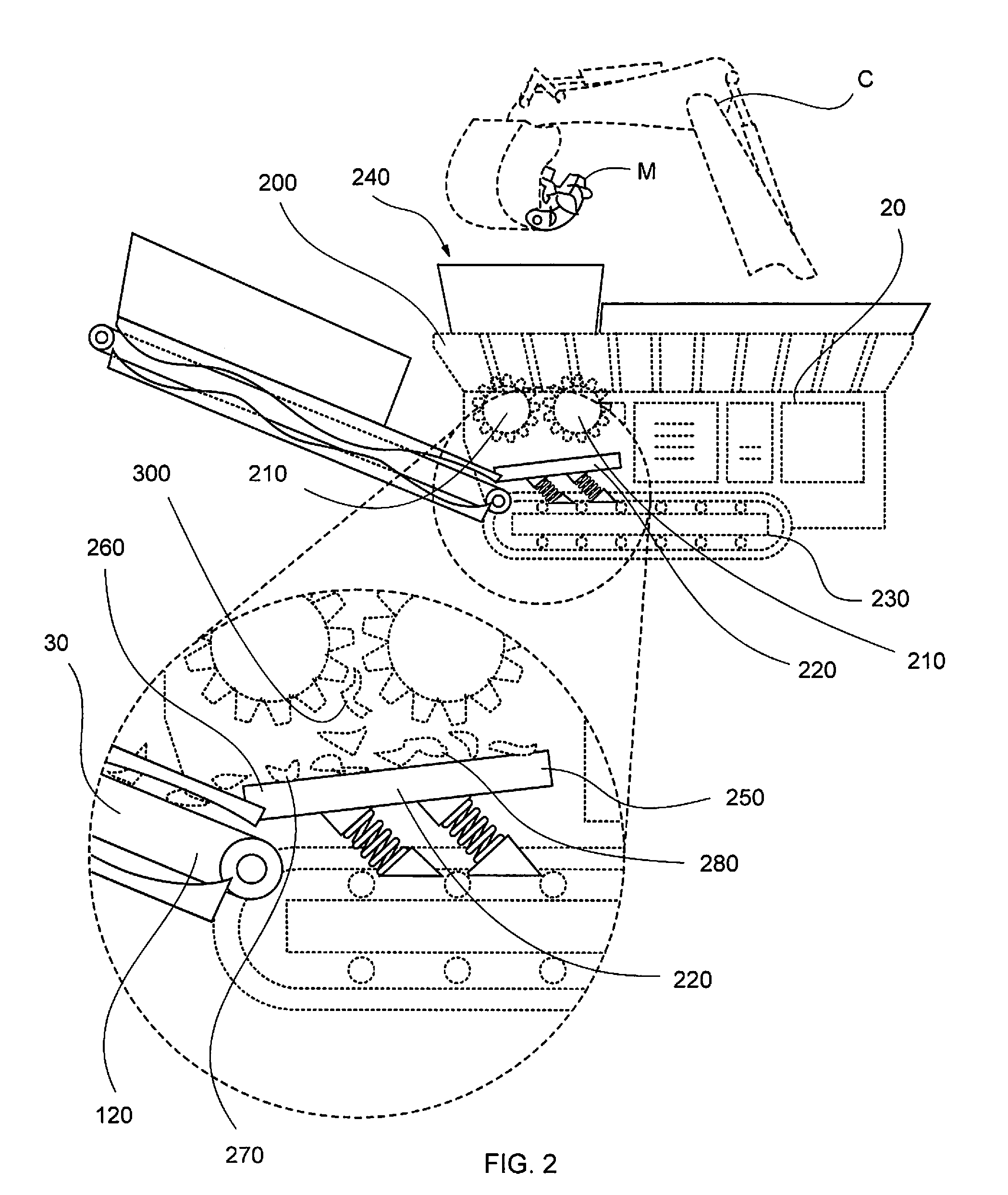
While all of the aforementioned devices are associated with separating and / or shredding materials, none of the aforementioned devices teach a shredder comprising a vibrating table disposed entirely within, thereby allowing the slowing decent of potentially damaging shredded objects onto a conveyor belt, while simultaneously dispensing the various sized objects more evenly onto the conveyor belt.

Method used


Image

  • Metal Recycling Separator and Method of Use Thereof
  • Metal Recycling Separator and Method of Use Thereof
  • Metal Recycling Separator and Method of Use Thereof

Examples


Embodiment Construction

[0057]In describing the preferred and selected alternate embodiments of the present invention, as illustrated in FIGS. 1-5, specific terminology is employed for the sake of clarity. The invention, however, is not intended to be limited to the specific terminology so selected, and it is to be understood that each specific element includes all technical equivalents that operate in a similar manner to accomplish similar functions.

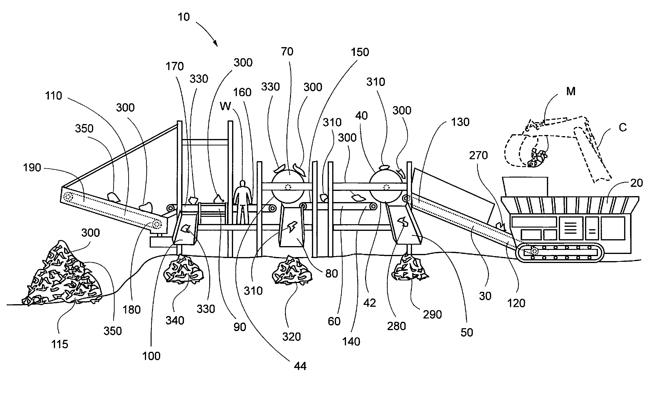
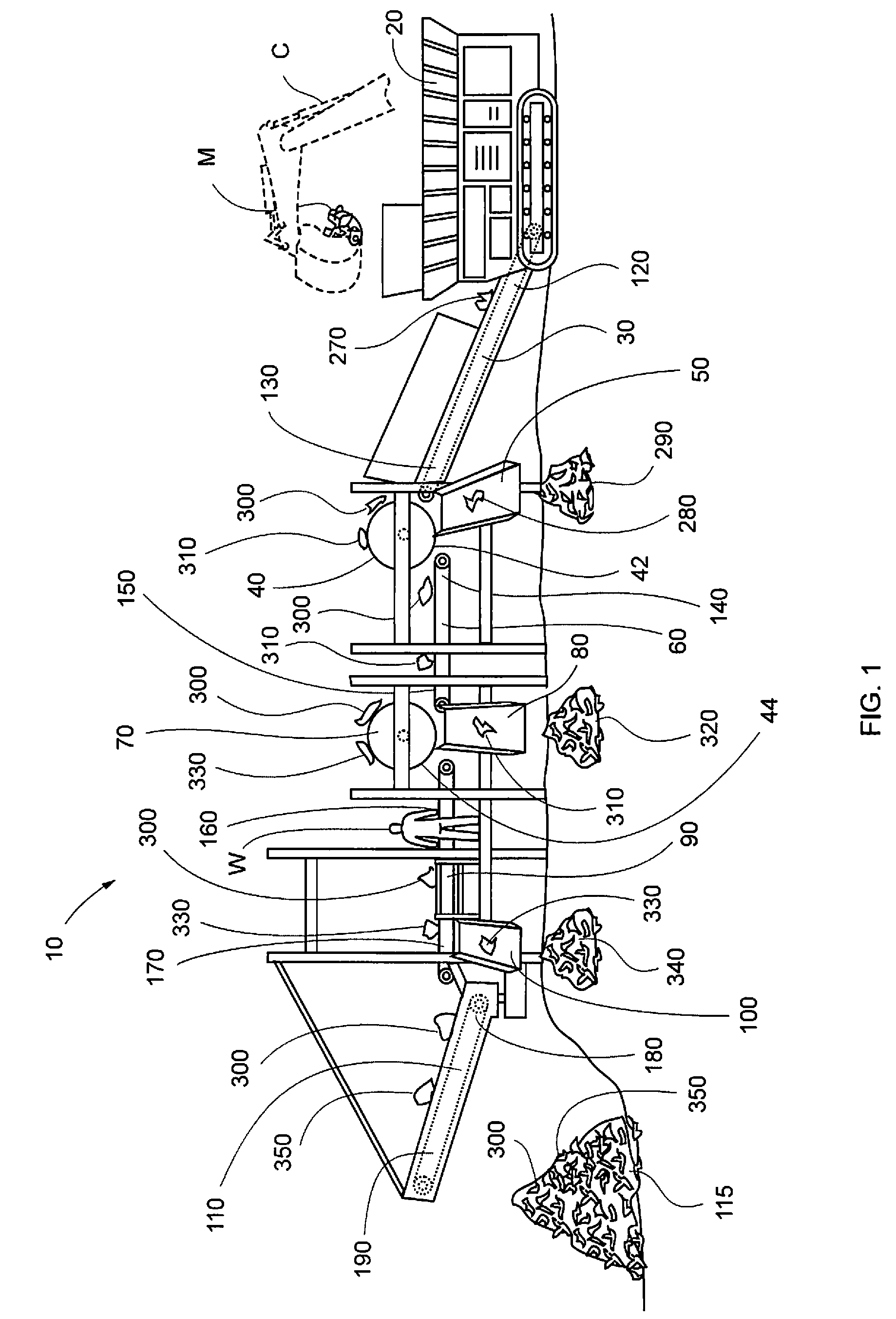
[0058]Referring to FIG. 1, first separating section 10 comprises shredder 20, first conveyor belt 30, first drum electromagnet 40, first sloped chute 50, flat shaking table 60, second drum electromagnet 70, second sloped chute 80, second conveyor belt 90, third sloped chute 100, third conveyor belt 110 and first collection section 115. First conveyor belt 30 comprises first end 120 and second end 130, wherein flat shaking table 60 comprises first edge 140 and second edge 150, and wherein second conveyor belt 90 comprises first end 160 and second end 170, and w...


PUM

PropertyMeasurementUnit
angleaaaaaaaaaa
resistance to corrosionaaaaaaaaaa
magnetic fieldaaaaaaaaaa

Abstract

A metal recycling separator comprising a shredder having a sloped shaking table disposed entirely within the shredder. The shredder shreds materials into ferrous and non-ferrous materials and the sloped shaking table disperses the ferrous and non-ferrous materials onto a first conveyor belt. Non-ferrous materials are separated from ferrous materials by conveying such through two drum electromagnets, wherein the ferrous material and the remaining non-ferrous materials are transferred to a water receptacle. The water receptacle is filled with water, wherein a part of the remaining non-ferrous materials float out of the water receptacle, and the remaining ferrous materials sink to the bottom of the water receptacle. The ferrous materials and residual non-ferrous materials are then conveyed out of the water receptacle and onto two conveyor belts and a third drum electromagnet. Ferrous material is removed from the two conveyor belts and is also removed via the third drum electromagnet.

Description

CROSS-REFERENCE TO RELATED APPLICATIONSNoneFEDERALLY SPONSORED RESEARCH OR DEVELOPMENTNonePARTIES TO A JOINT RESEARCH AGREEMENTNoneREFERENCE TO A SEQUENCE LISTINGNoneBACKGROUND OF THE INVENTION[0001]1. Technical Field of the Invention[0002]The preferred embodiment relates generally to a metal recycling separator and method of use thereof, and more specifically to separating ferrous and non-ferrous materials utilizing a shredder with a sloped shaking table disposed entirely within the shredder, a plurality of conveyor belts, a plurality of drum electromagnets and a water tank.[0003]2. Description of Related Art[0004]Garbage in landfills contain both ferrous and non-ferrous materials. Ferrous materials contain iron and are resistance to corrosion. Non-ferrous metal do not contain iron. Generally, it is beneficial to separate and recover ferrous materials from non-ferrous materials from a landfill site because ferrous materials may be re-utilized for building, manufacturing, tool makin...

Claims


Application Information

Patent Timeline
Patent Type & Authority Applications(United States)
IPC IPC(8): B03C1/30B02C23/00
CPCB02C21/00B02C23/08B03B9/06C22B7/005B03C1/08B03C1/30B03C1/0335Y02W30/52Y02P10/20
Inventor RUIZ, ARIEL
Owner RUIZ ARIEL
Learn More