
Spot welding system and dressing determination method

a technology of welding system and dressing, applied in the direction of electrode features, manufacturing tools, electrode maintenance, etc., can solve the problems of deteriorating reliability of determination results, and achieve the effects of improving reliability, accurate judgment, and simplifying the operation of quality determination results of the shaping process of the electrod

Active Publication Date: 2011-10-06
FANUC LTD
View PDF6 Cites 69 Cited by
  • Summary
  • Abstract
  • Description
  • Claims
  • Application Information

AI Technical Summary

Benefits of technology

The present invention provides a spot welding system and a method for determining the quality of a shaping process applied to an electrode of a welding gun. The system and method use a visual sensor to obtain images of the electrode before and after the shaping process, and calculate the difference between the two images to determine the cut amount of the electrode. The cut amount is then judged to be within or outside of a predetermined acceptable range, to determine the quality of the shaping process. This approach simplifies the quality determination operation and improves the reliability of the quality determination results, preventing poor welds caused by poorly shaped electrodes.

Problems solved by technology

In these methods, if the pulse signals of the encoder do not accurately represent the position of the electrode due to, e.g., vibrations generating when the electrode is driven, or if the tip diameter or length of the electrode includes errors due to, e.g., deviation of the attachment position of the electrode with respect to the welding gun, the reliability of determination results is deteriorated.

Method used


Image

  • Spot welding system and dressing determination method
  • Spot welding system and dressing determination method
  • Spot welding system and dressing determination method

Examples


Embodiment Construction

by a visual sensor in the spot welding system of FIG. 1;

[0016]FIG. 4 is a diagram schematically depicting a robot system according to an embodiment of the present invention, to which the spot welding system of FIG. 1 can be applied; and

[0017]FIG. 5 is a flowchart depicting a dressing determination method according to an embodiment of the present invention.

DETAILED DESCRIPTION

[0018]The embodiments of the present invention are described below, in detail, with reference to the accompanying drawings. In the drawings, same or similar components are denoted by common reference numerals.

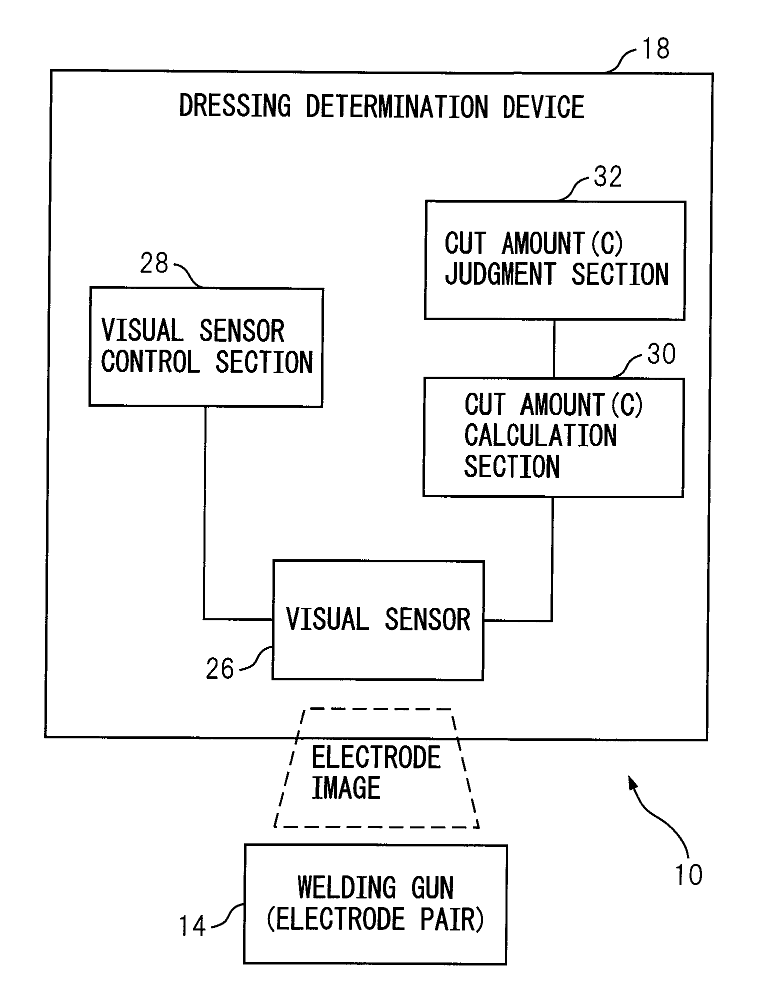
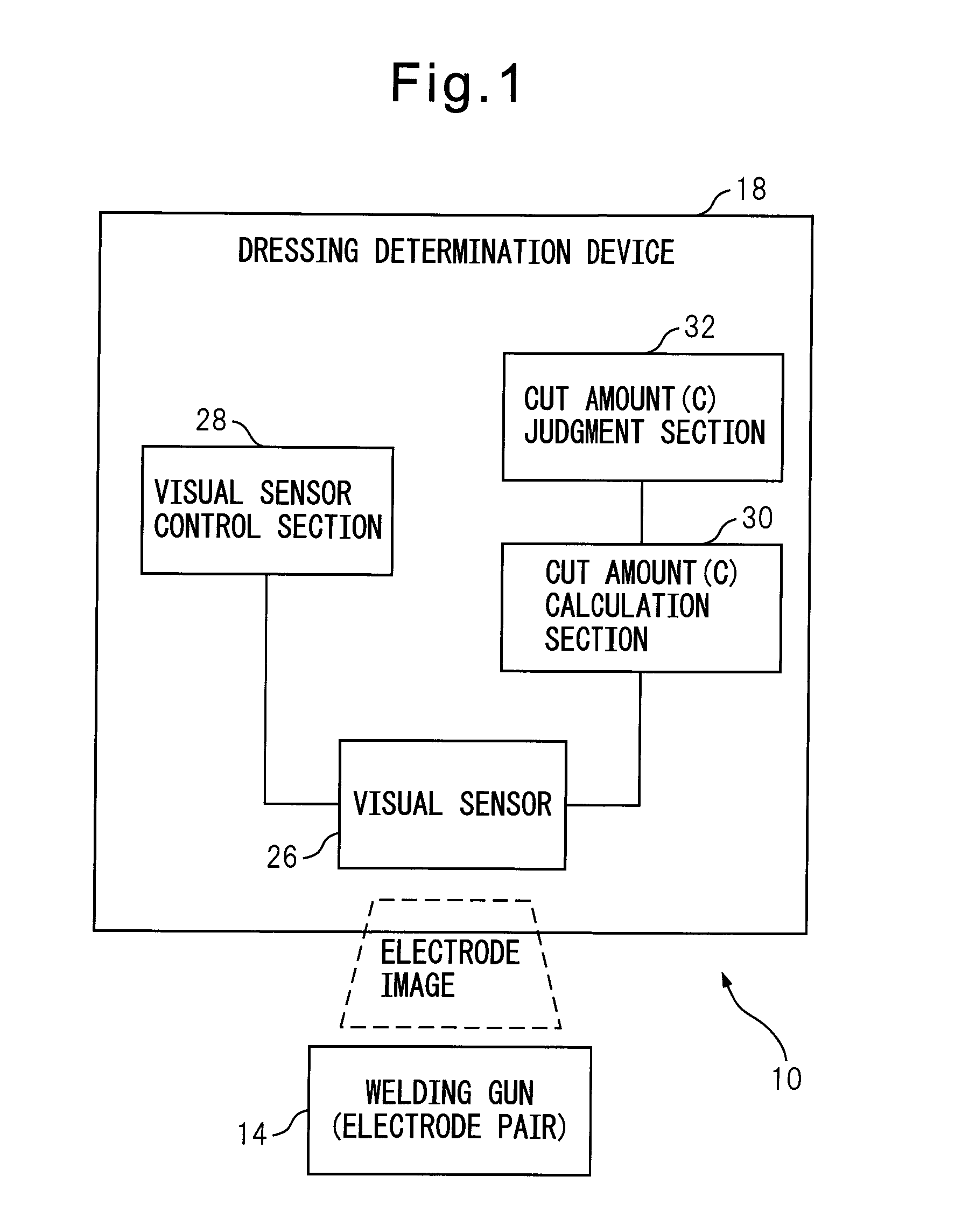
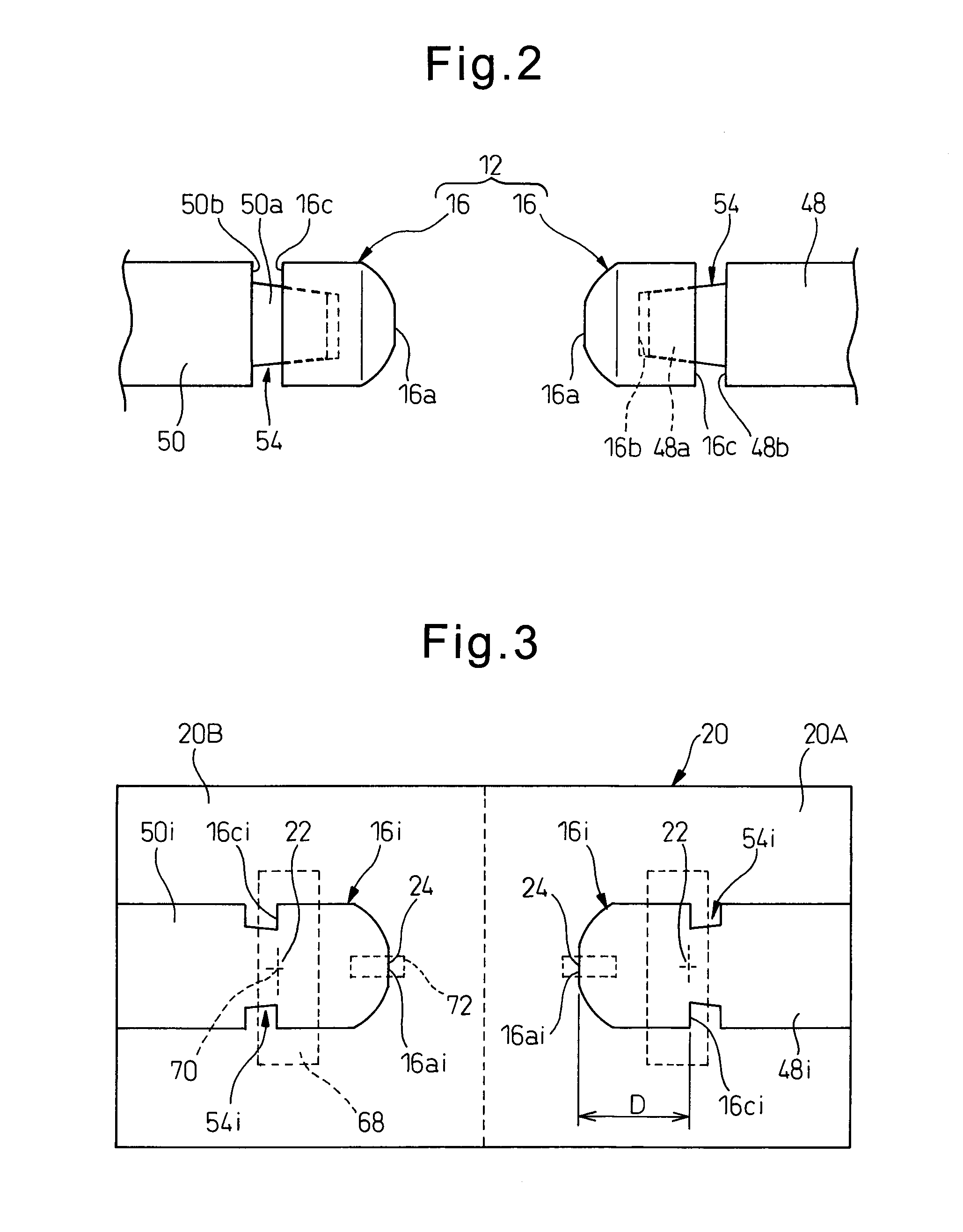
[0019]Referring to the drawings, FIG. 1 is a functional block diagram depicting a configuration of a spot welding system 10 according to an embodiment of the present invention, FIG. 2 is a diagram schematically depicting an electrode pair of a welding gun in the spot welding system 10, and FIG. 3 is a diagram depicting an image obtained by a visual sensor in the spot welding system 10.

[0020]The spot welding...


PUM

PropertyMeasurementUnit
distanceaaaaaaaaaa
image processingaaaaaaaaaa
rotational angleaaaaaaaaaa

Abstract

A spot welding system including a welding gun with an openable / closable electrode pair; and a dressing determination device determining a quality of a shaping process applied to an electrode of the electrode pair. The dressing determination device includes a visual sensor obtaining an image of the electrode, identifying a base and a tip of the electrode on the image and measuring a distance between the base and the tip on the image, by image processing; a visual sensor control section allowing the visual sensor to measure the distance immediately before and after the shaping process is performed; a cut amount calculation section calculating a difference between the distances measured by the visual sensor immediately before and after the shaping process is performed, as a cut amount of the electrode; and a cut amount judgment section judging whether the calculated cut amount is within a predetermined acceptable range.

Description

BACKGROUND OF THE INVENTION[0001]1. Field of the Invention[0002]The present invention relates to a spot welding system. The present invention also relates to a dressing determination method in the spot welding system.[0003]2. Description of the Related Art[0004]In a spot welding system, with respect to at least one pair of electrodes (hereinafter referred to as an electrode pair) provided in a welding gun, a shaping or forming process (typically referred to as a dressing) for restoring the surface of each electrode worn or deformed due to the repetition of a spot welding process to a proper shape is performed at required periods. In this connection, various dressing determination methods for determining the quality of the shaping process applied to the electrodes of the welding gun.[0005]For example, Japanese Unexamined Patent Publication (Kokai) No. 2002-219581 (JP2002-219581A) discloses “method and device for detecting an abnormality in a dressing of an electrode tip provided in a...

Claims


Application Information

Patent Timeline
Patent Type & Authority Applications(United States)
IPC IPC(8): B23K11/11
CPCB23K11/115B23K11/36B23K11/315B23K11/3063
Inventor TAKAYAMA, YUUSUKETAKAHASHI, HIROMITSU
Owner FANUC LTD
Learn More