Multi-joint cable protection and guide device

a multi-joint cable and guide device technology, applied in the direction of instruments, machine supports, other domestic objects, etc., can solve the problems of unnatural twisting or tensioning of cables, damage of cables and hoses, etc., to reduce the number of required parts, reduce the bending load, and reduce the damage of cables

Active Publication Date: 2011-10-06
TSUBAKIMOTO CHAIN CO
View PDF38 Cites 34 Cited by
  • Summary
  • Abstract
  • Description
  • Claims
  • Application Information

AI Technical Summary

Benefits of technology

[0019]According to the first aspect of the invention, the multi-joint cable protection and guide device has the flexible belt member. The flexible belt member includes a plurality of cable inserting tubular portions which are unitarily molded in parallel. A train comprises a plurality of block bodies that are flexibly connected with each other by concave-convex snap-fittings. The train of block bodies is inserted through at least one of the cable inserting tubular portions to control and support straight and flexed postures of the flexible belt member. It is unnecessary, due to this structure, to injection-mold pieces one by one with respect to a stainless steel member or a leaf spring as is done in the related art.
[0020]Accordingly, it is easy to connect and disconnect the multi-joint cable protection and guide device corresponding to its usage, as compared to the related art flexible member composed of a supporting member such as a stainless steel member which is difficult to cut.
[0021]Because the large numbers of block bodies are flexibly connected by the concave-convex snap-fittings, the multi-joint cable protection and guide device can steadily protect and guide the cables that assume flexed and straight postures.
[0022]Furthermore, it becomes possible to ...

Problems solved by technology

When the cables are connected to a mobile portion of a working machine such as a construction machine or a machine used for transportation, the cables ar...

Method used


Image

  • Multi-joint cable protection and guide device
  • Multi-joint cable protection and guide device
  • Multi-joint cable protection and guide device

Examples


Embodiment Construction

Preferred Embodiments

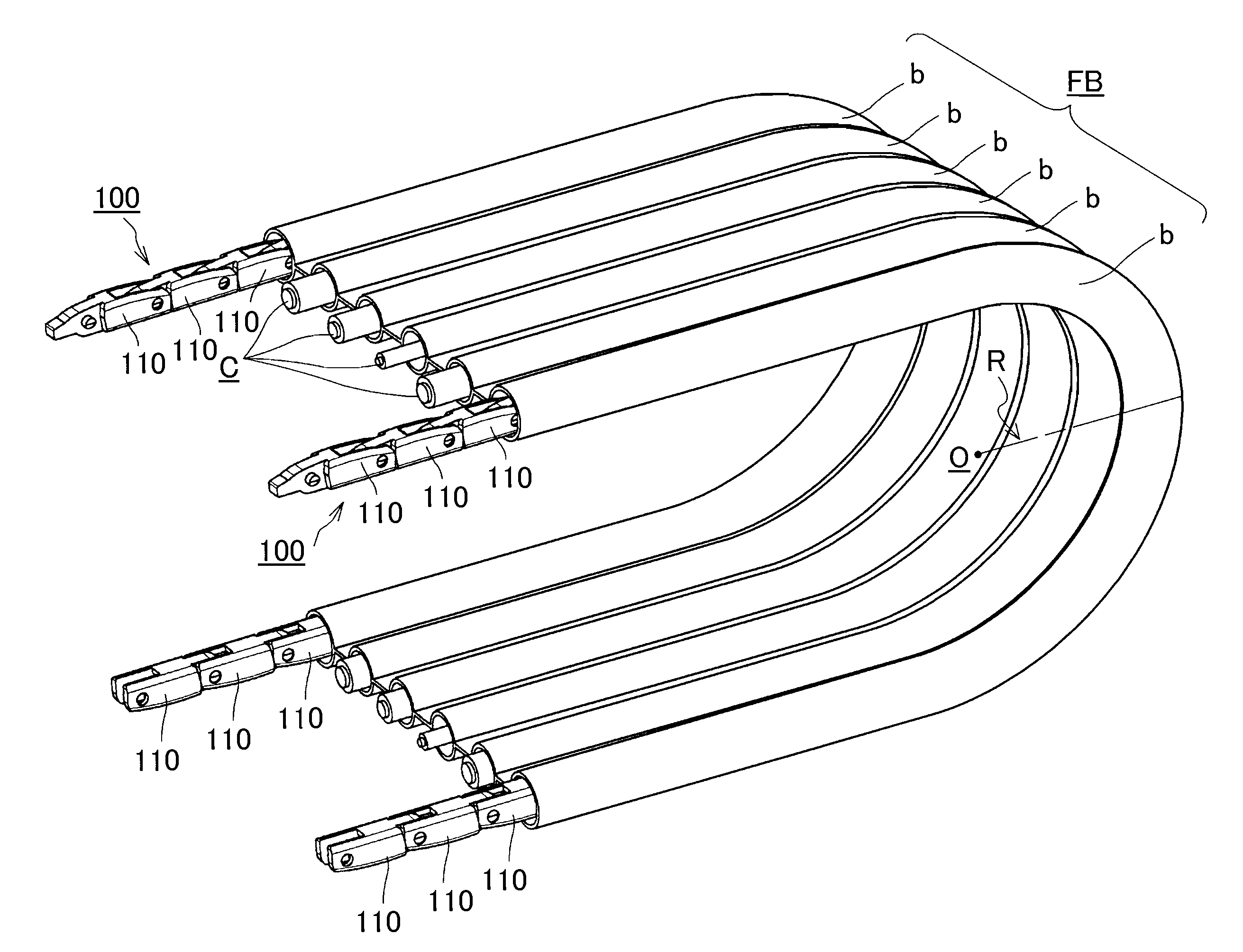
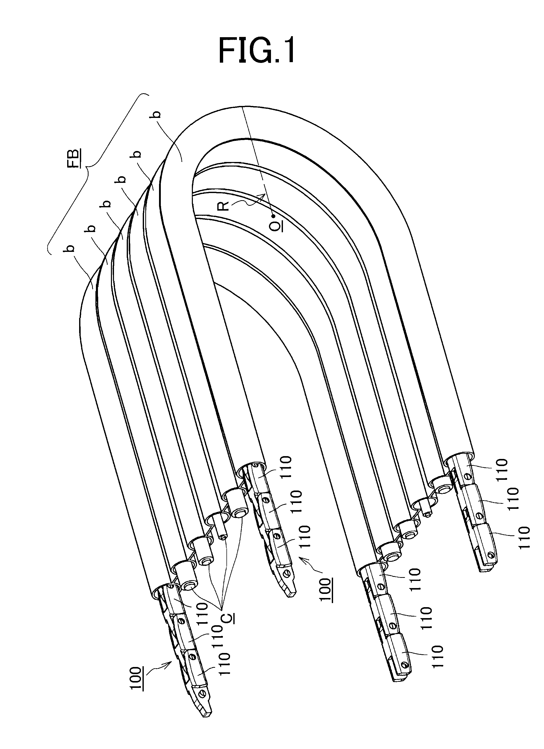
[0038]An embodiment of a multi-joint cable protection and guide device of the invention will be explained with reference to FIGS. 1 through 7.

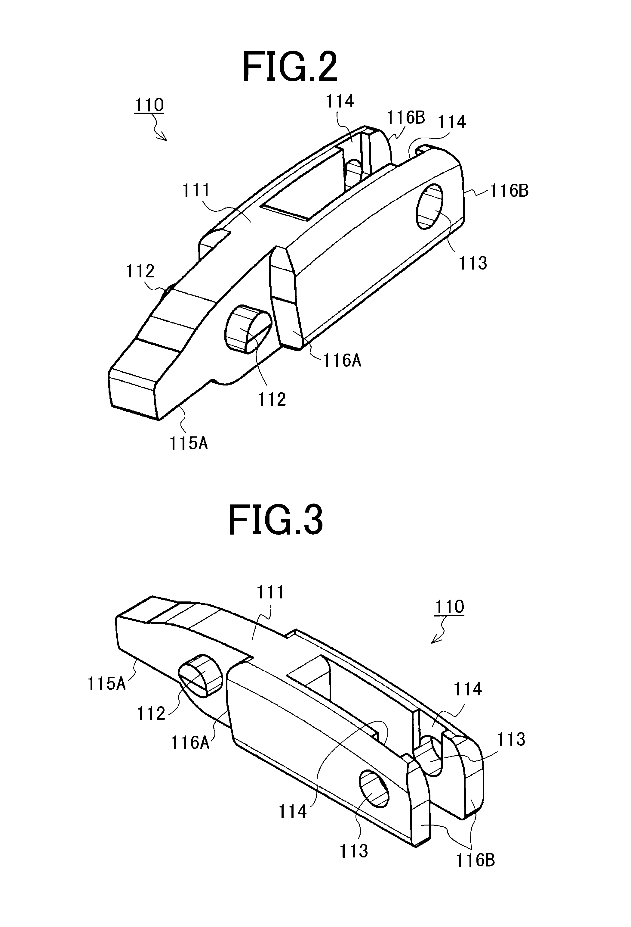
[0039]Here, FIG. 1 illustrates a mode of use of a multi-joint cable protection and guide device according to one embodiment of the invention. FIG. 2 is a perspective view of a block body shown in FIG. 1 seen from a front obliquely upward direction. FIG. 3 is a perspective view of a block body shown in FIG. 1 seen from a rear obliquely upward direction. FIG. 4 is an exploded view of the multi-joint cable protection and guide device shown in FIG. 1. FIG. 5 illustrates a bending state of the multi-joint cable protection and guide device shown in FIG. 1. FIG. 6 is a side view showing a straight state of the multi-joint cable protection and guide device. FIG. 7 is a side view showing a bending state of the multi-joint cable protection and guide device.

[0040]One embodiment of the multi-joint cable protection and guide device 100...


PUM


Abstract

There is provided a multi-joint cable protection and guide device that fits well with a flexible belt member in a flexed posture, that steadily protects and smoothly guides cables that assume the flexed posture, that requires fewer parts and that may be readily connected and disconnected corresponding as desired according to usage. The multi-joint supporting member has the flexible belt member in which cable inserting tubular portions are unitarily molded in parallel and a train comprising a plurality of block bodies flexibly connected with each other by concave-convex snap-fittings. The train of block bodies is inserted through the cable inserting tubular portions to control and support straight and flexed postures of the flexible belt member and each block body has a flexion outer peripheral-side curved surface whose curvature is equal to a radius of a flexed circular arc in the flexed posture.

Description

CROSS REFERENCE TO RELATED APPLICATIONS[0001]This application claims the foreign priority benefit under Title 35, United States Code, §119 (a)-(d) of Japanese Patent Application No. 2010-085693, filed on Apr. 2, 2010 in the Japan Patent Office, the disclosure of which is herein incorporated by reference in its entirety.BACKGROUND OF THE INVENTION[0002]1. Field of the Invention[0003]The present invention relates to a multi-joint cable protection and guide device for protecting and guiding flexible cables and hoses. The flexible cable may be an electrical cable or an optical fiber cable. The flexible hose may be a fluid supplying hose. The cables and hoses may be used in working machines, electronic devices, industrial robots, and transportation equipment. The cables and hoses supply electricity, fluid, and air machines or to a mobile section of a machine.[0004]2. Related Art[0005]When the cables are connected to a mobile portion of a working machine such as a construction machine or ...

Claims


Application Information

Patent Timeline
IPC IPC(8): F16L3/22
CPCF16G13/20H02G11/006G02B6/4461H02G3/0487F16L3/00
Inventor KOMIYA, SHOICHIRO
Owner TSUBAKIMOTO CHAIN CO
Why Eureka
Try Eureka