Magnetic Shield for Stator Core End Structures of Electric Rotating Machine

a stator core and shield technology, applied in the direction of dynamo-electric machines, magnetic circuits characterised by magnetic materials, magnetic circuit shapes/forms/construction, etc., can solve the problems of reducing efficiency, increasing heat generation, and leaking flux in a relatively large amount, so as to reduce the loss of clamping plates and shields.

Inactive Publication Date: 2011-10-06
HITACHI LTD
View PDF0 Cites 10 Cited by
  • Summary
  • Abstract
  • Description
  • Claims
  • Application Information

AI Technical Summary

Benefits of technology

[0022]According to the electric rotating machine of the present inventi...

Problems solved by technology

In the meantime, since the clamping plates are generally made of iron and magnetized, a relatively large amount of flux leakage can flow into the clamping plates from the rotor and the stator winding as the sources of magnetic flux.
In addition, since the clamping plates are massive, eddy current caused by the inflow magnetic flux is large to cause a problem of an increase in heat generation due to eddy current loss and hence reduction in efficiency.
Meanwhile, when the magnetic flux flows from the stacking direction, eddy current flows into the steel sheet planes, causing great eddy current loss.
The technique in the above-mentioned publication could cause eddy current loss because the magnetic flux flows into the magnetic shield from the stacking direction.
As mentioned above, use of the powder magnetic core can suppresses the eddy current loss, but the powder magnetic core has lo...

Method used


Image

  • Magnetic Shield for Stator Core End Structures of Electric Rotating Machine
  • Magnetic Shield for Stator Core End Structures of Electric Rotating Machine
  • Magnetic Shield for Stator Core End Structures of Electric Rotating Machine

Examples


embodiment 1

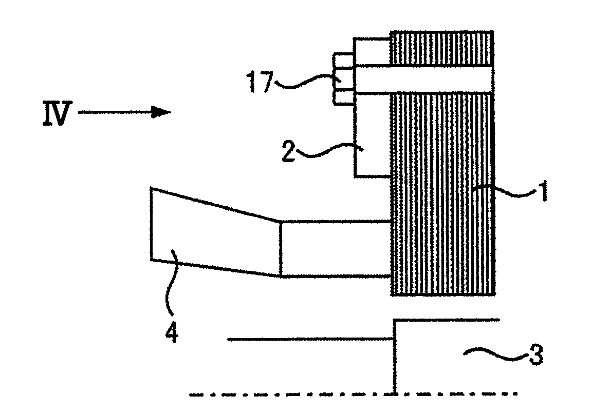
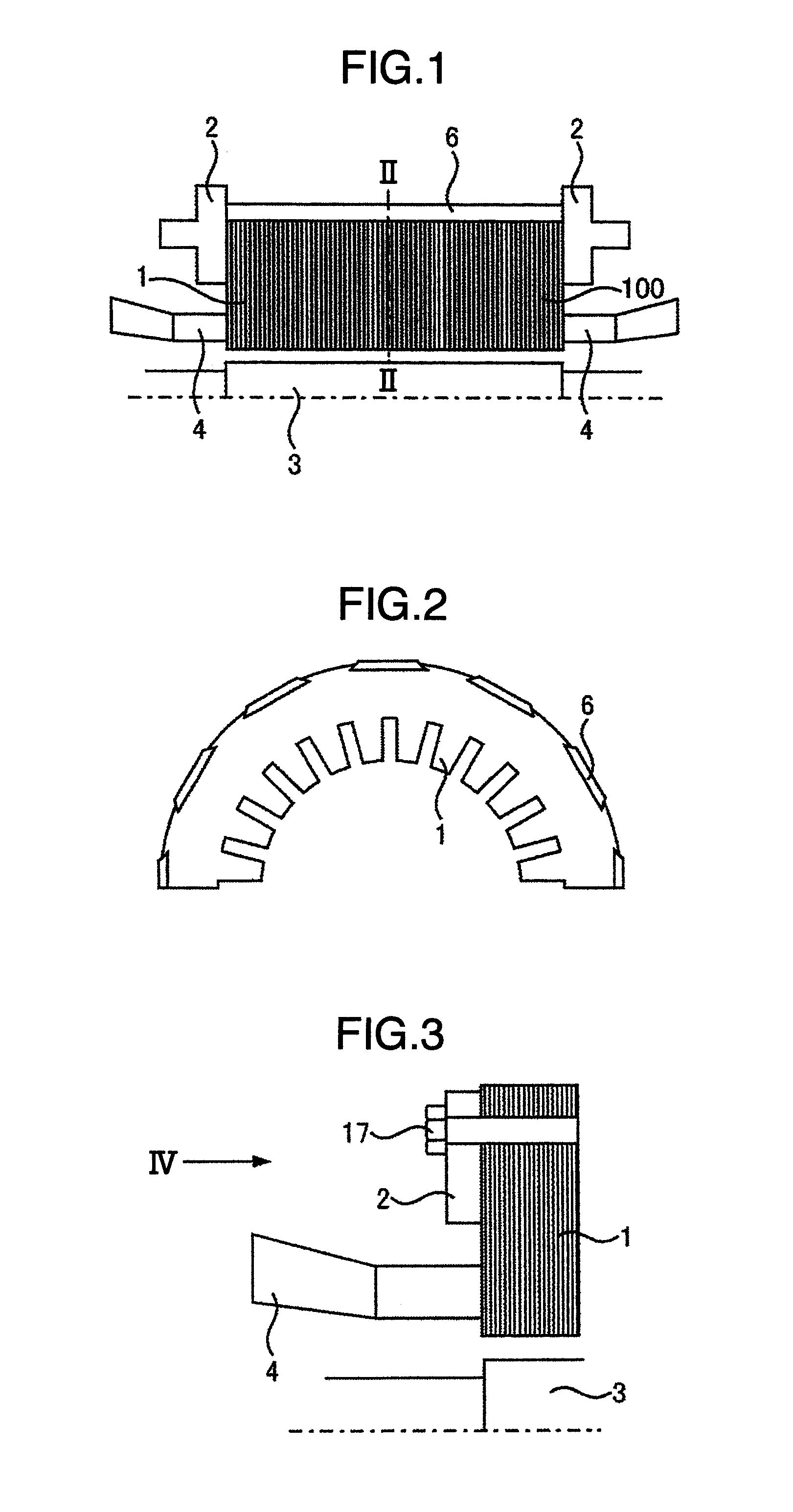
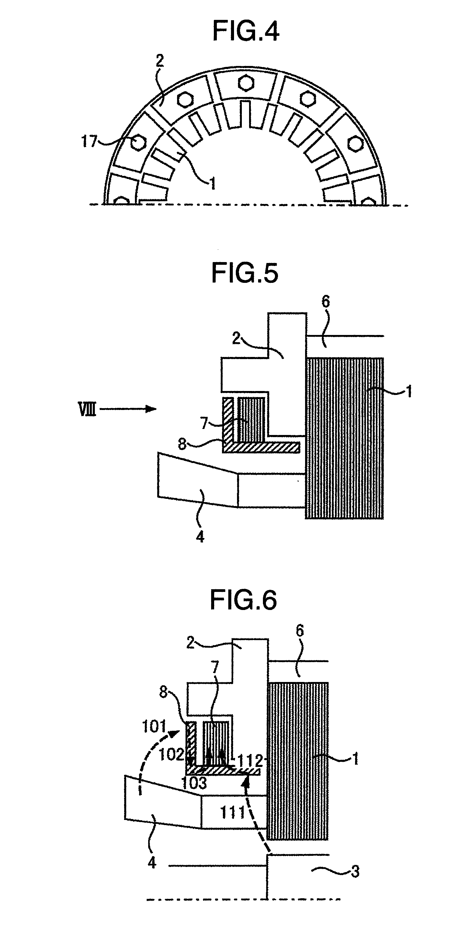
[0066]FIG. 5 shows a stator end part of a turbine generator as an example of an electric rotating machine to which the present invention is applied.

[0067]As shown in the drawing, in this Embodiment, a magnetic shield using a cylinder 7 of stacked steel sheets stacked in the shape of a cylinder about a rotor shaft and a powder magnetic core segment 8 formed by compressing powder of dielectrically-coated magnetic material is attached to clamping plates 2 clamping a stator core 1 from both end parts in the stacking direction of magnetic steel sheets. This magnetic shield is arranged outside the outer side of radial direction of a stator winding 4 to cover the lateral sides and inner surface of radial direction of the clamping plates 2. When the magnetic shield is attached to the clamping plates 2, air gaps or nonmagnetic insulators are provided in the axial direction between the cylinder 7 of stacked steel sheets and the clamping plates 2 and between the cylinder 7 of stacked steel she...

embodiment 2

[0088]As shown in FIG. 9, the surface of each of the powder magnetic core segments 8 in Embodiment 1 is covered with resin or each of the powder magnetic core segments 8 is housed in a resin case 9 for a single segment so as to prevent iron powder of the powder magnetic core from scattering. Further, as shown in FIG. 10 and FIG. 11, multiple powder magnetic core segments 8 are housed in a resin case 19 for multiple segments so that the number of parts can be reduced, making the setting easy.

[0089]Further, in order to prevent the powder magnetic core segments 8 from moving in the case 19, grooves 18 may be formed in the case 19 as shown in FIG. 12.

embodiment 3

[0090]As shown in FIG. 13, this embodiment is structured that an end duct spacers 5 which make ventilation paths are arranged between the stator core 1 and the clamping plates 2 in the axial direction.

[0091]In this embodiment, the end duct spacers 5 make heat-absorbing ventilation ducts are made between the stator core 1 and the clamping plates 2, thereby improving cooling performance.

[0092]Further, as shown in FIG. 14, a groove is formed in an end face of the end duct spacer 5 in the axial direction and the powder magnetic core segment 8 is extended to the groove portion in the axial direction, so that magnetic flux that enters the clamping plates 2 from the end duct spacer 5 can be attracted to the powder magnetic core segment 8, thereby further reducing more loss in the clamping plates 2.


PUM


Abstract

In an electric rotating machine, for reducing losses that occur in clamping plates and their shield, the electric rotating machine includes a rotor formed with field winding wound around a rotor core, a stator placed opposite to the rotor at a predetermined space and formed with stator winding wound around a stator core formed by stacking multiple magnetic steel sheets in the axial direction, clamping plates clamping and retaining the stator core from both axial end parts thereof in the stacking direction of the magnetic steel sheets, and a magnetic shield placed around the clamping plates to shield flux leakage flowing into the clamping plates, and the magnetic shield is formed of a cylinder of stacked steel sheets stacked in a form of a cylinder about the rotor shaft and powder magnetic core segments and powder magnetic core segments having portions which are stuck to the cylinder of stacked steel sheets on the stacking cross section, and arranged to cover side surfaces and an inner surface of radial direction of the clamping plates.

Description

BACKGROUND OF THE INVENTION[0001](1) Field of the Invention[0002]The present invention relates to an electric rotating machine. For example, it relates to an electric rotating machine suitable for a structure in which a stator core adopted in a turbine generator or the like as a large electric rotating machine is formed by stacking plural magnetic steel sheets and clamped by clamping plates which apply presser on a stator core in a stacking direction from axial end parts.[0003](2) Description of Related Art[0004]A conventional example will be described by taking, as an example, a turbine generator as a large electric rotating machine.[0005]FIG. 1 and FIG. 2 show the schematic structure of the turbine generator. The turbine generator shown in the figures is constituted roughly of a rotor 3 formed by winding field winding around a rotor core and a stator 100 placed opposite to this rotor 3 at a predetermined space and formed by winding stator winding 4 around a stator core 1.[0006]The...

Claims


Application Information

Patent Timeline
IPC IPC(8): H02K1/18H02K1/02
CPCH02K2213/03H02K3/42H02K1/12
Inventor YOSHIDA, JUNNAKAHARA, AKIHITOKOMURA, AKIYOSHI
Owner HITACHI LTD
Why Eureka
Try Eureka