
Cassegrain antenna for high gain

a high-gain, antenna technology, applied in the direction of antennas, electrical equipment, etc., can solve the problems of high manufacturing cost and high manufacturing cost, and achieve the effect of reducing manufacturing cos

Inactive Publication Date: 2011-10-06
ELECTRONICS & TELECOMM RES INST
View PDF1 Cites 6 Cited by
  • Summary
  • Abstract
  • Description
  • Claims
  • Application Information

AI Technical Summary

Benefits of technology

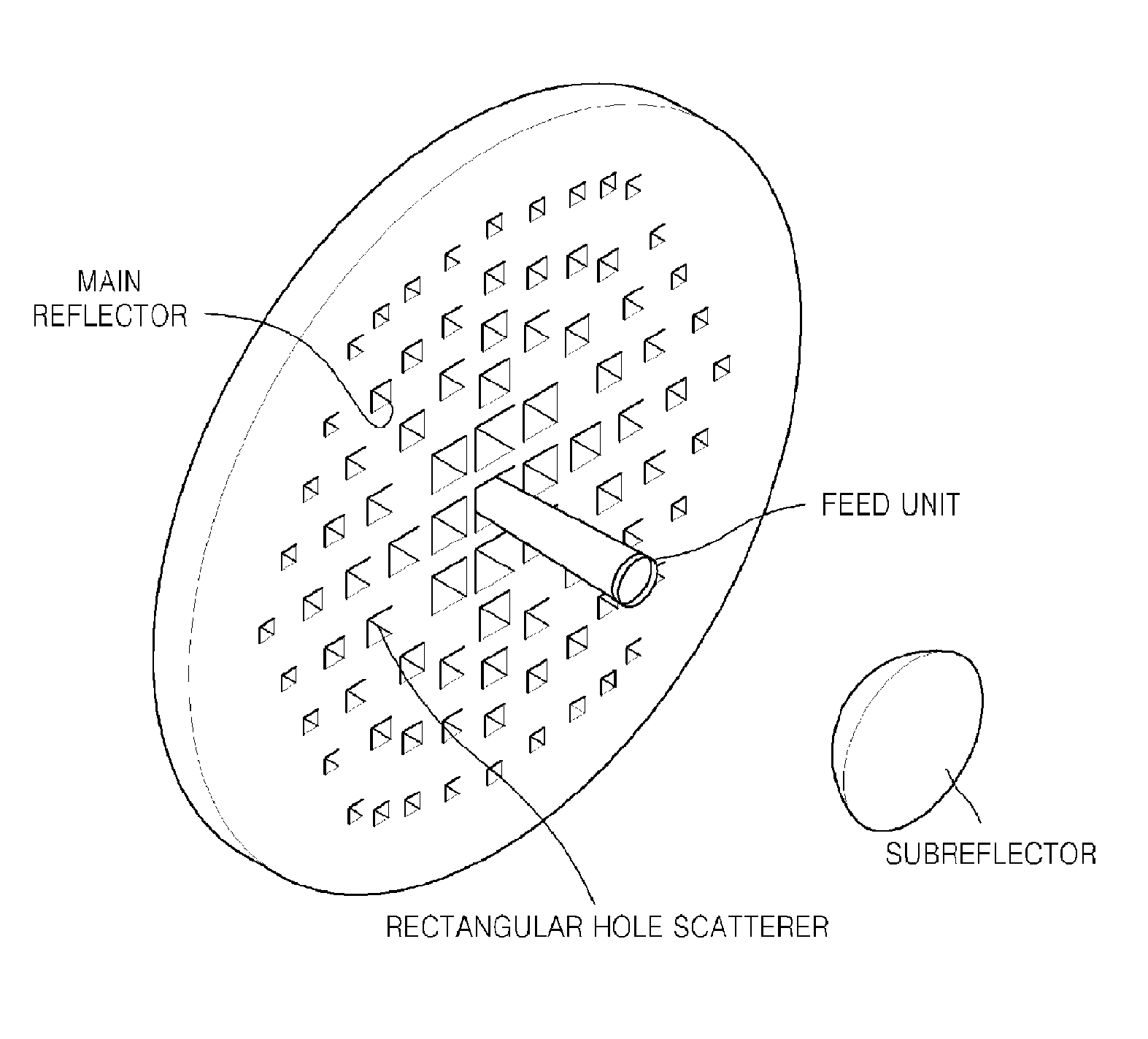
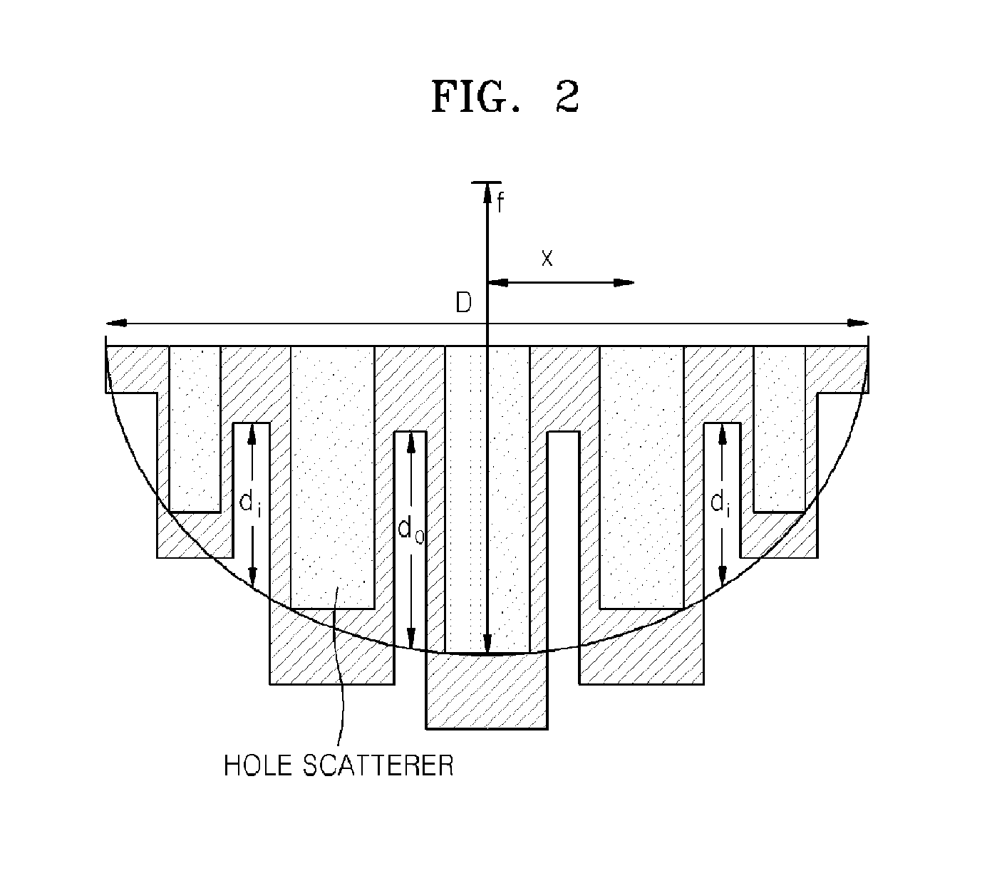
[0008]According to the below embodiments, a Cassegrain antenna includes a main reflector having hole scatterers of different depths and a subreflector having protruding scatterers of different heights. Accordingly, it is possible to greatly reduce manufacturing costs in implementing a high-gain broadband antenna.

Problems solved by technology

The parabolic reflector antenna is disadvantageous in that manufacturing costs thereof are high, and thus, it is needed to reduce the manufacturing costs by using a flat reflector antenna.

Method used


Image

  • Cassegrain antenna for high gain
  • Cassegrain antenna for high gain
  • Cassegrain antenna for high gain

Examples


Embodiment Construction

[0020]The objectives, characteristics, and advantages of the present invention will be apparent from the following description and the accompanying drawings. In the following description, well-known functions or constructions are not described in detail if it is determined that they would obscure the invention due to unnecessary detail. Hereinafter, exemplary embodiments of the present invention will be described in detail with reference to the attached drawings.

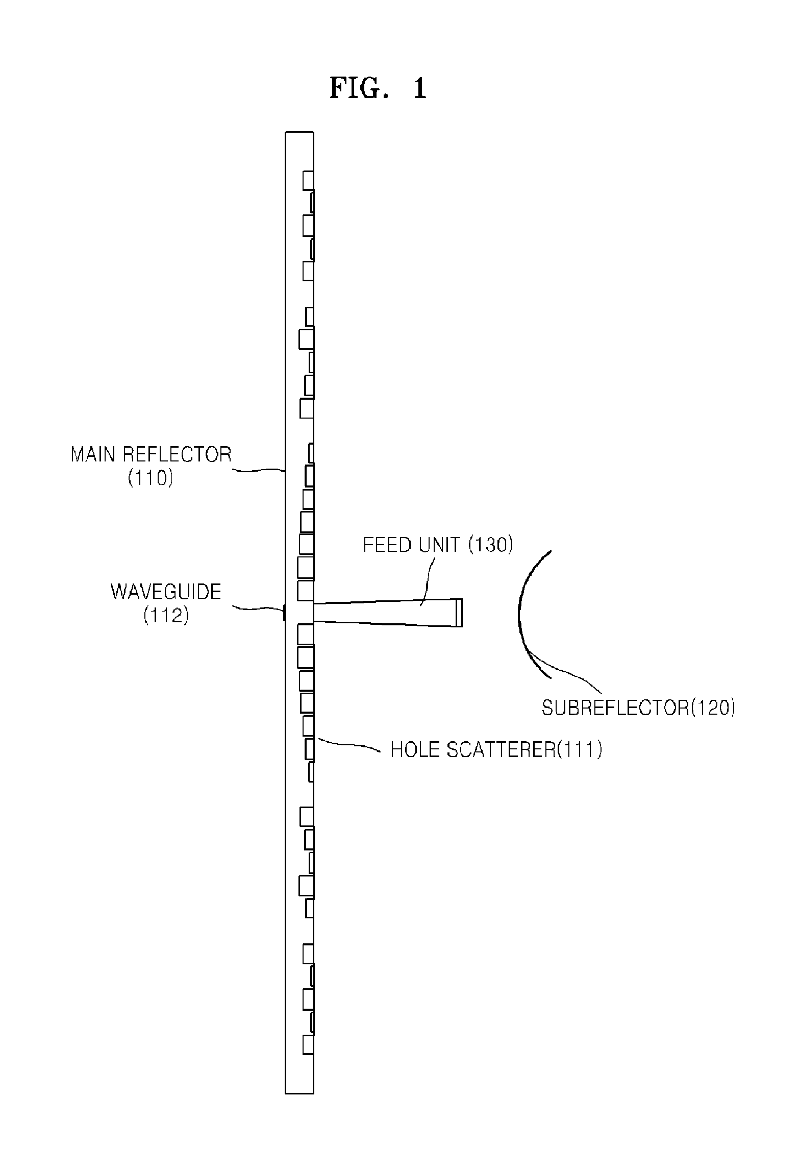
[0021]FIG. 1 is a diagram illustrating the structure of a Cassegrain antenna according to an embodiment of the present invention. Referring to FIG. 1, the Cassegrain antenna includes a main reflector 110, a subreflector 120, and a feed unit 130.

[0022]In the main reflector 110, a plurality of hole scatterers 111 of different depths are formed in a surface of the main reflector 110 facing the subreflector 120. The hole scatterers 111 scatter incident electromagnetic waves, and are formed by mechanically drilling holes in a met...


PUM


Abstract

Provided is a high gain Cassegrain antenna. The antenna includes a feed unit that radiates radio waves, a subreflector that faces a radiation surface of the feed unit and reflects the radiated radio waves, and a main reflector that has a plurality of hole scatterers of different depths facing the subreflector and reflecting again the radio waves reflected from the subreflector. Accordingly, it is possible to manufacture a high-gain broadband antenna at low costs.

Description

TECHNICAL FIELD[0001]The present invention relates to a Cassegrain antenna for high gain, and more particularly, to a Cassegrain antenna having a main reflector in which a plurality of irregularities are formed to have hole scatterers of different depths so that the antenna can operate in microwave and military wave bands.BACKGROUND ART[0002]A parabolic antenna is a high-gain reflector antenna used for wireless, television, radar, and data communications. In general, the parabolic antenna has a parabolic reflector illuminated by a small feed antenna.[0003]The reflector has a metallic surface of a parabolic shape, and the feed antenna is located at a focus of the reflector.[0004]The parabolic reflector antenna is disadvantageous in that manufacturing costs thereof are high, and thus, it is needed to reduce the manufacturing costs by using a flat reflector antenna.DISCLOSURE OF INVENTIONTechnical Problem[0005]A conventional flat reflector antenna has a kind of parabolic shape, in whic...

Claims


Application Information

Patent Timeline
IPC IPC(8): H01Q19/18
CPCH01Q3/46H01Q19/193H01Q19/19H01Q19/062
Inventor BYUN, WOO-JINCHO, YOUNG-HEULSONG, MYUNG-SUNKIM, BONG-SUKIM, KWANG-SEONKANG, MIN-SOO
Owner ELECTRONICS & TELECOMM RES INST
Learn More