Contamination monitoring of high voltage insulators

a technology of high-voltage insulators and monitoring devices, which is applied in the direction of closed-circuit television systems, color television details, television systems, etc., can solve problems such as insulator flashover, operating problems, and dry band formation in high-current areas

Inactive Publication Date: 2011-10-06
KING FAHD UNIVERSITY OF PETROLEUM AND MINERALS
View PDF16 Cites 18 Cited by
  • Summary
  • Abstract
  • Description
  • Claims
  • Application Information

AI Technical Summary

Benefits of technology

[0010]The system and method for contamination monitoring of high voltage insulators provides an early predictor for high voltage insulator failure, allowing repairmen to either already be on site when a high voltage insulator fails in order to expedite repair time, or allowing repair and / or replacement of a faulty insulator before the failure actually occurs. The system and method for contamination monitoring of high voltage insulators transmits an alarm signal when contaminant levels (such as equivalent salt deposit density (ESDD) levels) formed on a high voltage insulator exceed pre-selected threshold values, indicating the likelihood of high voltage insulator failure.

Problems solved by technology

This current heats the surfaces, leading to formation of dry bands in areas of high current density.
High voltages then build up across those bands, which may cause partial discharges, leading to insulator flashover.
Insulator surface contamination, and subsequent flow of leakage current, has caused operating problems for electric power utilities since electrical power has been in use.
Detection of a failed or contaminated insulator requires either visual inspection or disruption of the normal electrical power supply.
In other words, failure must first occur before repairs can be made.
Insulator contamination is often a result of exposure to various pollution types, including desert sandstorms, airborne salt from the sea, industrial pollution, high humidity and fog, in addition to high ambient temperatures and large ambient temperature differences within a 24-hour cycle.
The practice of periodic insulator washing is not particularly cost effective, due to the fact that insulator performance is determined by a number of parameters, some of which are variable and mostly unpredictable.

Method used


Image

  • Contamination monitoring of high voltage insulators
  • Contamination monitoring of high voltage insulators
  • Contamination monitoring of high voltage insulators

Examples


Embodiment Construction

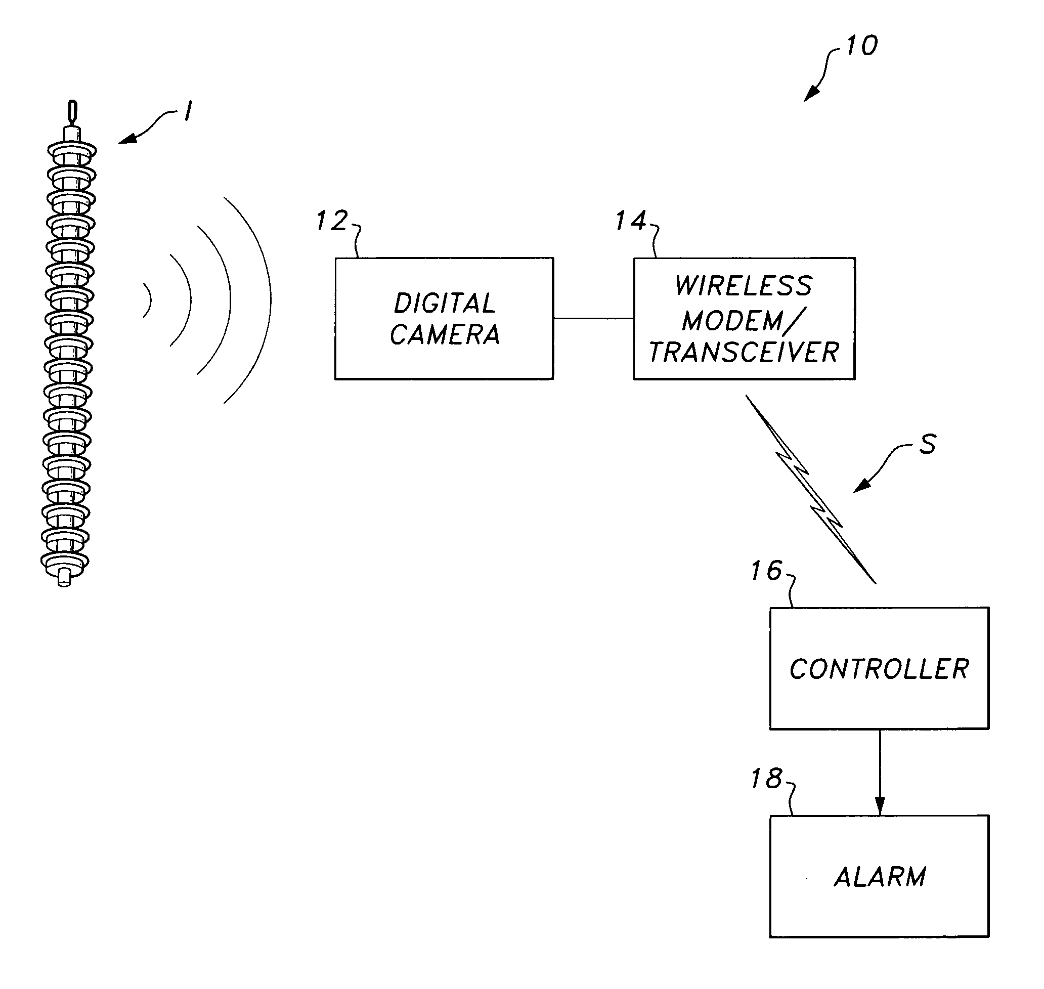
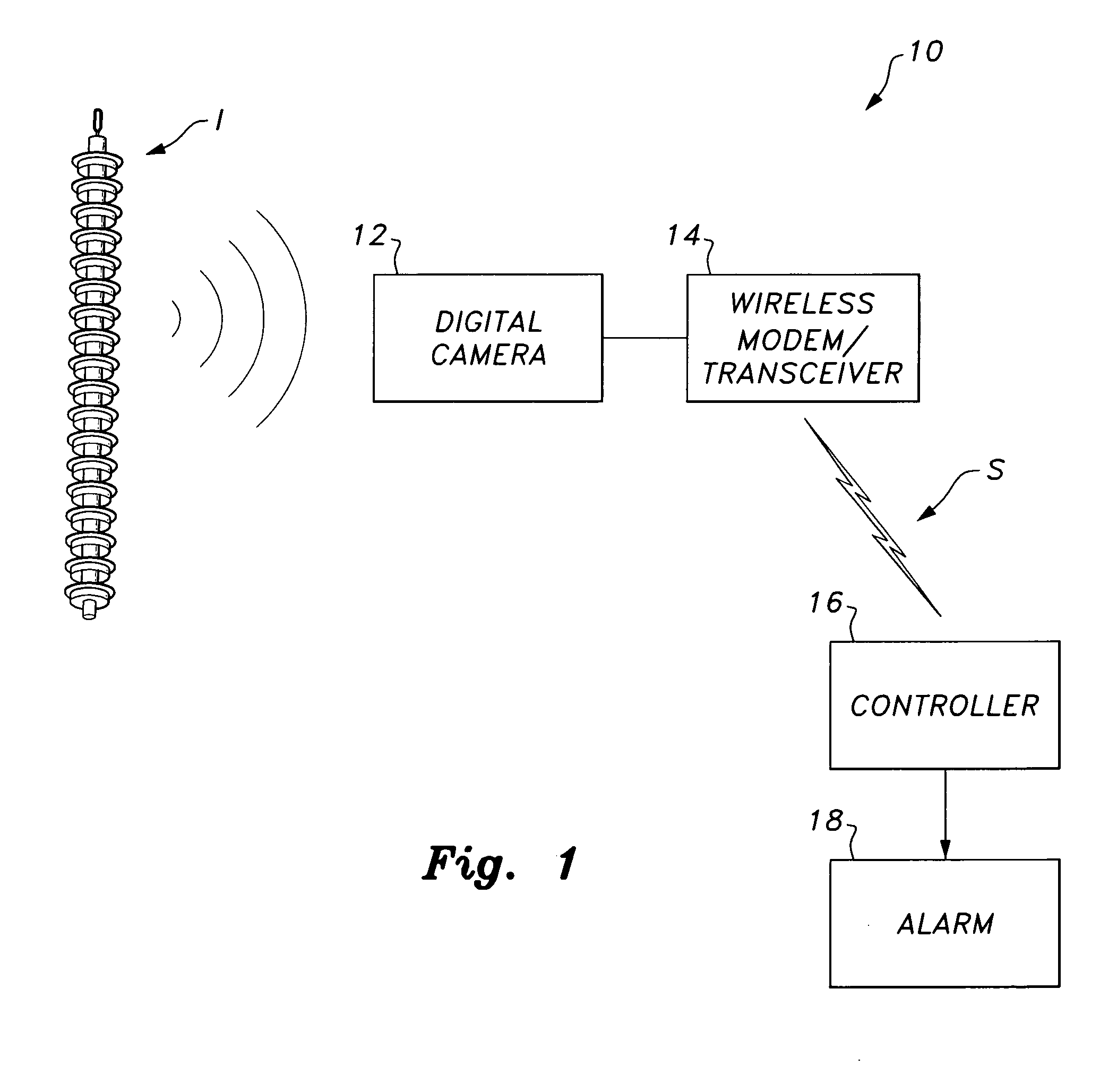
[0019]As best shown in FIG. 1, a system for contamination monitoring of high voltage insulators 10 provides an early predictor for high voltage insulator failure, allowing repairmen to either already be on site when a high voltage insulator, such as exemplary insulator I, fails in order to expedite repair time, or allowing repair and / or replacement of a faulty insulator I before the failure actually occurs. As will be described in greater detail below, the system for contamination monitoring of high voltage insulators 10 transmits an alarm signal when contaminant levels (such as equivalent salt deposit density (ESDD) levels) formed on the high voltage insulator exceed pre-selected threshold values, indicating the likelihood of high voltage insulator failure.

[0020]As shown in FIG. 3, a controller 16 is provided, with computer readable memory 22 being associated therewith. A database of equivalent salt deposit density eigenvalues is stored in computer readable memory 22. It should be ...


PUM


Abstract

Contamination monitoring of high voltage insulators provides a system and method producing an early predictor for high voltage insulator failure, allowing repairmen to either already be on site when a high voltage insulator fails in order to expedite repair time, or allowing repair and / or replacement of a faulty insulator before the failure actually occurs. The system and method provide transmission of an alarm signal when contaminant levels (such as equivalent salt deposit density (ESDD) levels) formed on a high voltage insulator exceed pre-selected threshold values, indicating the likelihood of high voltage insulator failure.

Description

BACKGROUND OF THE INVENTION[0001]1. Field of the Invention[0002]The present invention relates to the maintenance of high-voltage electrical equipment, and particularly to a system and method for contamination monitoring of high voltage insulators that provides for transmission of an alarm signal when contaminant levels (such as equivalent salt deposit density (ESDD) levels) formed on a high voltage insulator exceed pre-selected threshold values, indicating the likelihood of high voltage insulator failure.[0003]2. Description of the Related Art[0004]FIG. 2 illustrates a typical high voltage insulator I. Conventional high voltage transmission lines L typically use modular cap and pin insulators, such as high voltage insulator I. The wires or lines L are suspended from a string of substantially identical disc-shaped insulators D that are attached to each other with metal clevis pin or ball-and-socket links. The advantage of this design is that insulator strings with different breakdown...

Claims


Application Information

Patent Timeline
Patent Type & Authority Applications(United States)
IPC IPC(8): H04N7/18
CPCH04N7/183
Inventor AL-DUWAISH, HUSSAIN N.AL-HAMOUZ, ZAKARIYA M.MOUSA, WAIL A.AL-ABSI, MUNIR A.ZUMMO, SALAM A.
Owner KING FAHD UNIVERSITY OF PETROLEUM AND MINERALS
Why Eureka
Try Eureka