
Filter, image pickup lens, image pickup apparatus, and portable terminal device

Active Publication Date: 2011-10-06
FUJIFILM CORP
View PDF5 Cites 15 Cited by
  • Summary
  • Abstract
  • Description
  • Claims
  • Application Information

AI Technical Summary

Benefits of technology

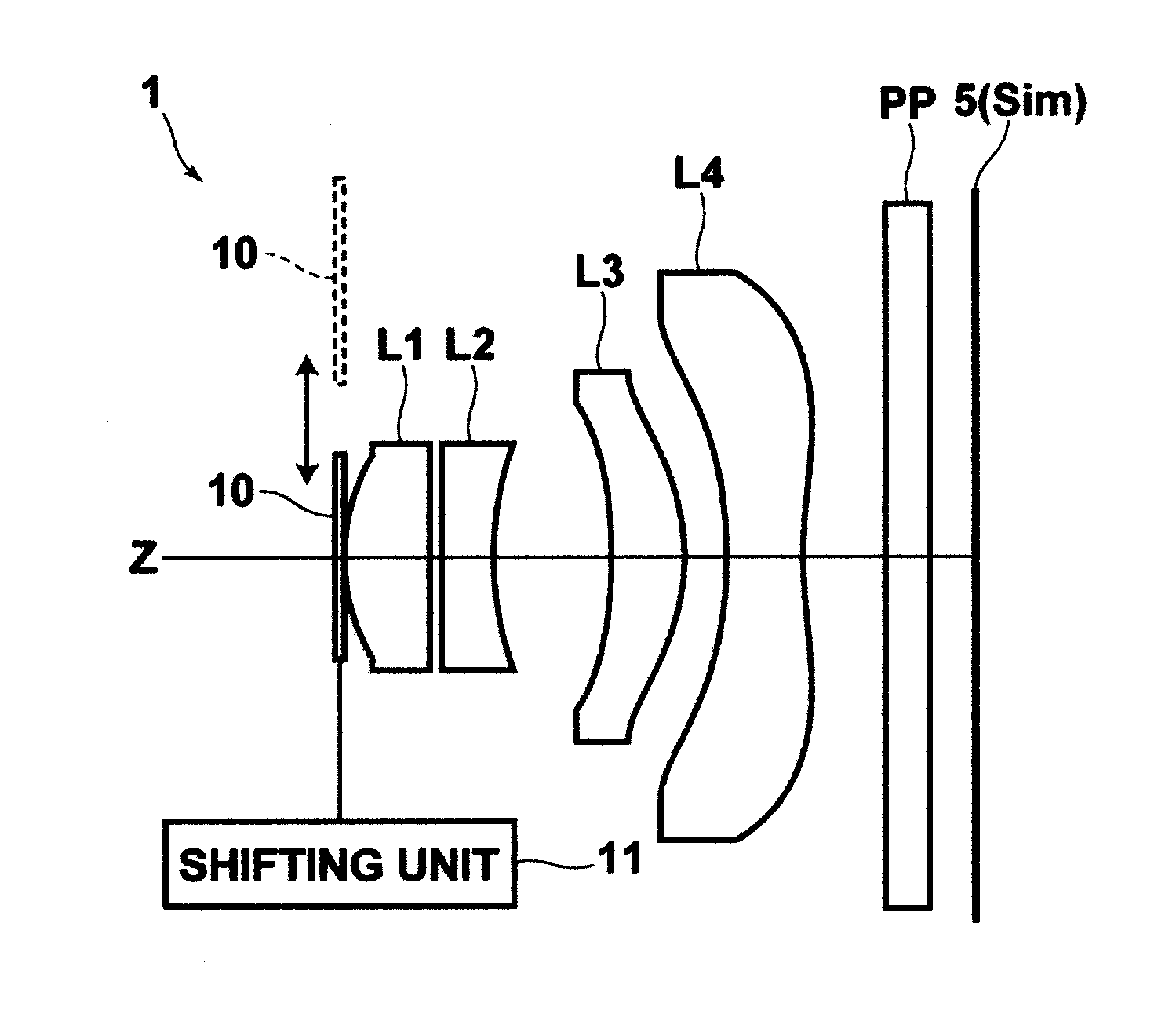
[0011]A filter of the present invention is a filter to be disposed concentrically with an optical axis of an imaging lens to exhibit an apodization effect or a peripheral light intensity correction effect,

Problems solved by technology

When decreasing or increasing the light transmission rate according to the distance from the center of the optical axis in a direction perpendicular to the optical axis, the apodization filter or the peripheral light intensity correction filter can not efficiently exhibit the apodization effect or the peripheral light intensity correction effect unless the light transmission rate is changed accurately according to a predetermined rule.
Conventional filters have difficulties in accurately changing the light transmission rate due to problems of accuracy in arranging a pattern of dots or concentric circles and in printing or applying the pattern.
Such problems are more significant, in particular, for filters used in small image pickup apparatuses incorporated in portable terminals and the like.

Method used


Image

  • Filter, image pickup lens, image pickup apparatus, and portable terminal device
  • Filter, image pickup lens, image pickup apparatus, and portable terminal device
  • Filter, image pickup lens, image pickup apparatus, and portable terminal device

Examples


example 1

[0071]Table 1 summarizes lens data and other data of image pickup lens 1 according to Example 1. Note that the lens configuration is identical to that shown in FIG. 1. In the lens data shown in Table 1, surface number 1 represents a surface of a component disposed at a position closest to the object side and surface number i represents an ith surface from the object side, which is gradually incremented for a surface of a component disposed closer to the image side (i=1, 2, 3, - - - ). The lens data shown in Table 1 include data of aperture position and optical member PP.

[0072]Radius of curvature i represents a radius of curvature of ith (i=1, 2, 3, - - - ) surface, and surface separation i represents a surface separation between ith (i=1, 2, 3, - - - ) surface and ith+1 surface on optical axis Z. Ndj represents a refractive index of jth optical element for d line, the number j being gradually incremented from the optical element disposed at a position closest to the object side towa...


PUM


Abstract

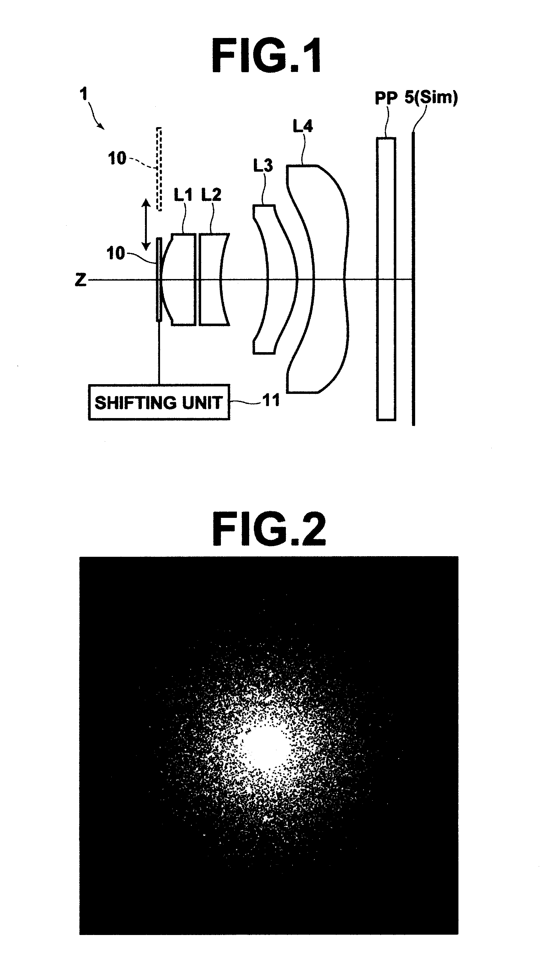
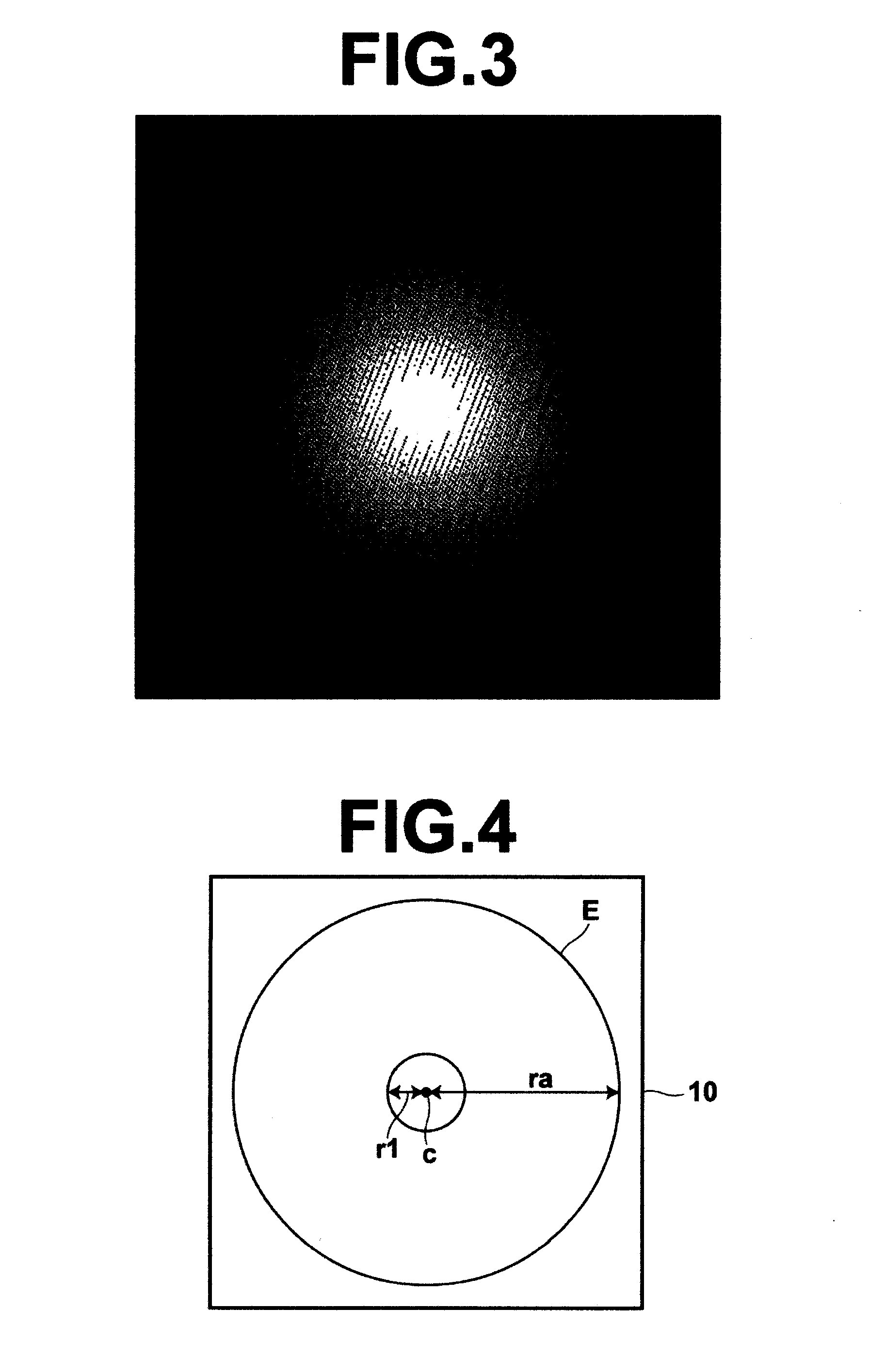
A filter, to be disposed concentrically with an optical axis of an imaging lens, capable of accurately controlling light transmission variation characteristics and effectively providing an apodization effect or a peripheral light intensity correction effect. The filter includes opaque dots disposed according to a honeycomb arrangement from a central portion toward a peripheral portion so as to have, at least partially, a Gaussian distribution like dot density and is structured to satisfy Condition Expression (1) given below when a size of the dots is taken as d.0.003 mm≦d≦0.010 mm  (1)

Description

BACKGROUND OF THE INVENTION[0001]1. Field of the Invention[0002]The present invention relates to an image pickup lens used for an image pickup apparatus incorporated in a portable terminal device or the like, and more particularly to a filter to be disposed concentrically with an optical axis of an imaging lens to exhibit an apodization effect or a peripheral light intensity correction effect.[0003]2. Description of the Related Art[0004]Generally, the performance of image pickup lenses is evaluated by the imaging capability at the focal plane. Consequently, a number of proposals with respect to aberration corrections for improving the imaging capability have been made. In addition to the imaging capability, it is also very important for image pickup lenses used in cameras, appearances of out-of-focus images (foreground blur and background blur). For example, in a portrait photograph with a person arranged in the center or a photograph of a flower obtained by macro photography, the i...

Claims


Application Information

Patent Timeline
IPC IPC(8): G02B5/20G02F1/13G02B3/00G03B11/04G03B17/14G03B30/00
CPCG03B11/00G02B13/18
Inventor SHINOHARA, YOSHIKAZU
Owner FUJIFILM CORP
Learn More