Broadband transceiver and distributed antenna system utilizing same

a distributed antenna and transceiver technology, applied in the direction of digital transmission, duplex signal operation, independent non-interaction antenna combination, etc., can solve the problems of large device size and high cost of duplexers, remote units using such duplexers are frequency limited, and require several expensive and bulky duplexers

Active Publication Date: 2011-10-06
COMMSCOPE TECH LLC
View PDF12 Cites 61 Cited by
  • Summary
  • Abstract
  • Description
  • Claims
  • Application Information

AI Technical Summary

Benefits of technology

For isolation, the receive antenna is positioned on the RF impermeable layer structure above the transmit antenna. Alternatively, the transmit antenna might be positioned above the receive antenna. In an alternative embodiment, a plurality of receive antennas and/or a plurality of transmit antennas might be located on the respective face surfaces of the transceiver or layer structure. For further isolation between the antennas the layer structure includes an RF choke positioned on the layer structure between the opposing

Problems solved by technology

There are drawbacks, however, in using a duplexer to do such signal combining.
First, duplexers are large devices and are expensive.
Second, duplexers achieve their isolation by using fixed filters tuned to the specific frequencies that are sh

Method used


Image

  • Broadband transceiver and distributed antenna system utilizing same
  • Broadband transceiver and distributed antenna system utilizing same
  • Broadband transceiver and distributed antenna system utilizing same

Examples


Embodiment Construction

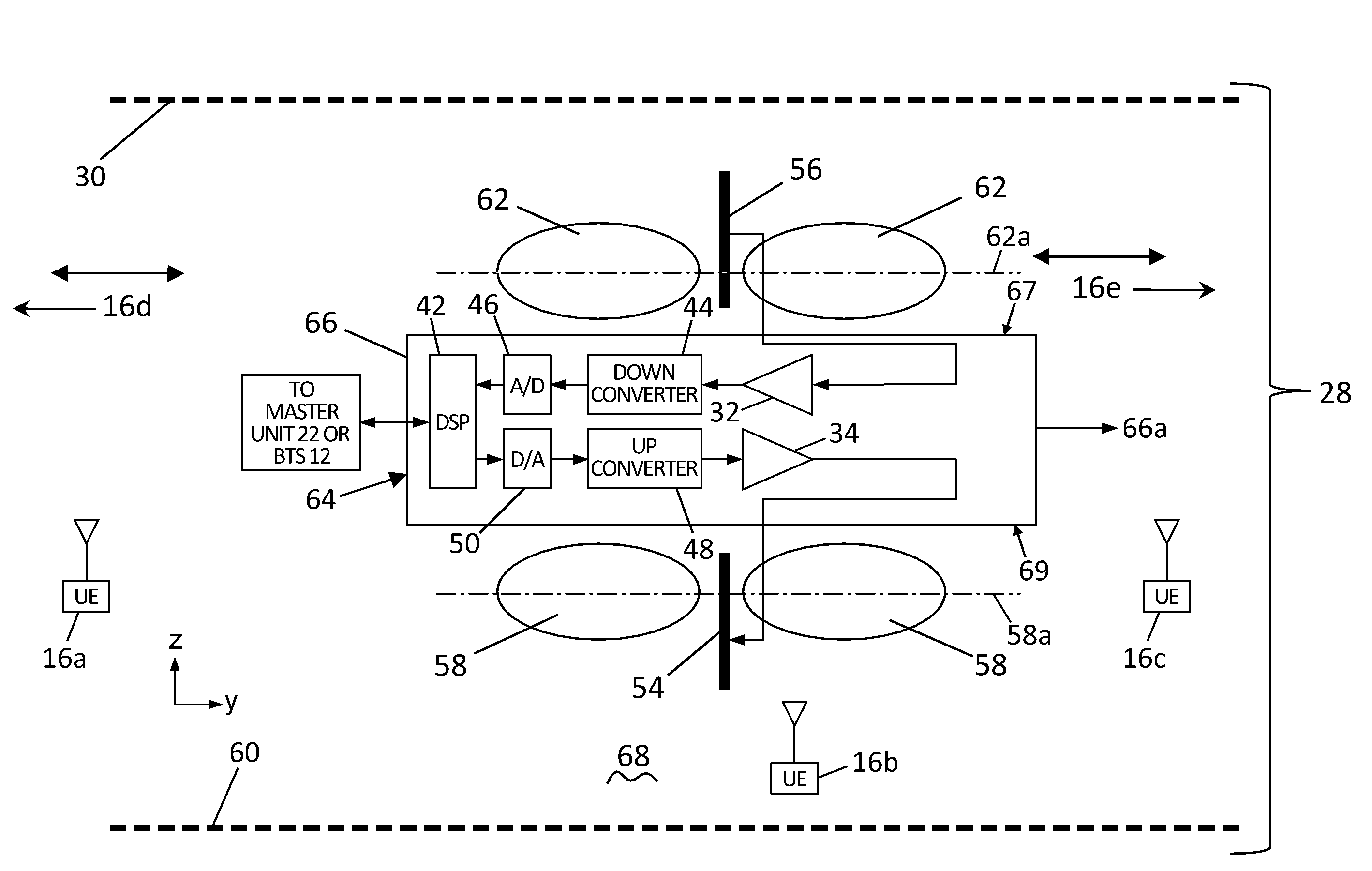
Embodiments of the invention provide a broadband transceiver, such as for use with a distributed antenna system (DAS) that does not employ the use of a duplexer. To provide the isolation needed between the transmitter and receiver, embodiments of the invention employ using two antennas, one for transmit and one for receive. Embodiments of the invention also provide the needed isolation between the two antennas while still providing the required antenna coverage for transceiver or any remote units of a DAS.

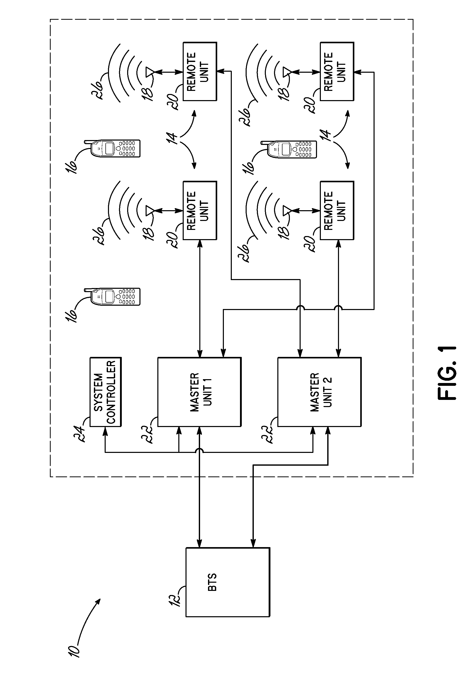
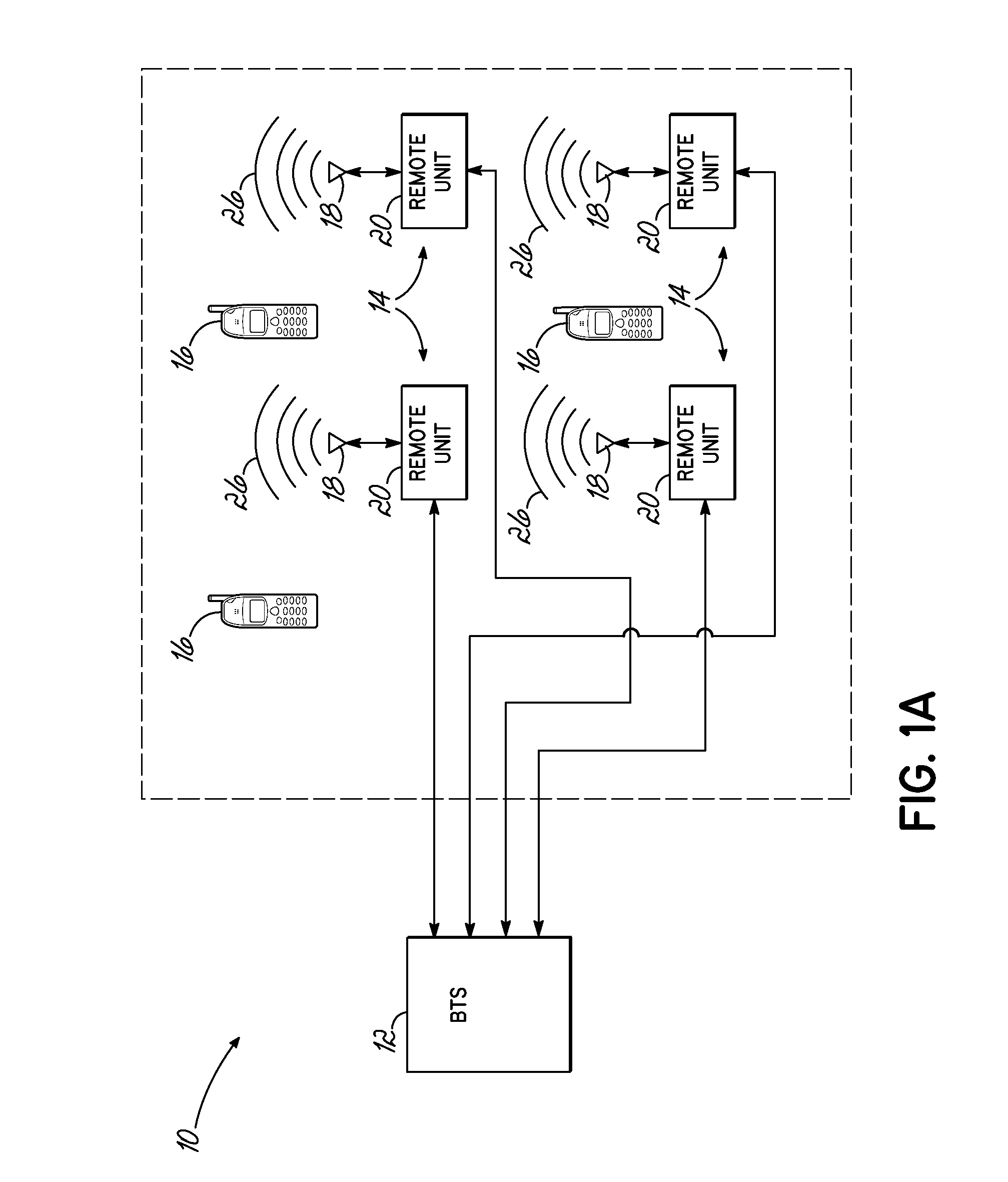
FIG. 1 illustrates an exemplary signal repeating system that may incorporate embodiments of the invention. Specifically, FIG. 1 illustrates a schematic diagram for an exemplary distributed antenna system (DAS) 10. The DAS 10 may be appropriately coupled to at least one base station (BTS), such as BTS 12 in a wired or wireless fashion. The DAS 10 might be incorporated into an area, such as a building environment, and thus, includes a number of remote antenna units 14 that are distri...


PUM


Abstract

A broadband transceiver includes at least one layer structure that is substantially impermeable to RF radiation. The layer structure includes a first face surface substantially opposite a second face surface. A receive antenna is located proximate the first face surface and configured to receive RF transmissions. A transmit antenna is located proximate the second surface and configured to transmit RF transmissions. At least one of the receive and transmit antennas generates a generally toroidal radiation pattern that is stronger in a direction substantially parallel to the respective layer structure face surface compared to a direction substantially perpendicular to the face surface.

Description

FIELD OF THE INVENTIONThe present invention relates generally to wireless transceiver systems and particularly to such systems for use in repeaters or distributed antenna systems.BACKGROUND OF THE INVENTIONIn existing wireless technologies, signal repeating devices, such as repeaters or distributed antenna systems (DAS), are used to extend the coverage of an overall wireless system beyond the range of traditional base stations. For example, an overall cellular or wireless communication system may consist of a plurality of base transceiver stations (BTS) or base stations that communicate with each other and with user equipment, such as cellular phones, to provide a defined coverage area. In such coverage areas, there are often smaller geographical areas that have very low signal coverage, as provided by one or more of the base stations. For example, such areas of low signal coverage may be within buildings or in areas that are otherwise obstructed, such as by terrain features or man-...

Claims


Application Information

Patent Timeline
IPC IPC(8): H04B1/38H01Q1/52
CPCH01Q1/007H01Q21/30H01Q21/28H01Q1/525
Inventor PHILLIPS, FRED WILLIAMKUMMETZ, THOMASIZZAT, NARIAN
Owner COMMSCOPE TECH LLC
Why Eureka
Try Eureka