
Method and system for determining the position of an optic cup boundary

a technology of optic cup boundary and method, applied in the field of method and system for determining optic cup boundary, can solve the problems of difficult to use such a method and the possibility of performing the techniqu

Inactive Publication Date: 2011-10-06
SINGAPORE HEALTH SERVICES PTE +2
View PDF0 Cites 8 Cited by
  • Summary
  • Abstract
  • Description
  • Claims
  • Application Information

AI Technical Summary

Benefits of technology

[0011]In general terms, the present invention proposes that kinks in blood vessels approximately at the boundary between the optic cup and the optic disc are used to identify the edges of the optic cup. Certain embodiments of the invention thus make possible a computerized system to identify the optic cup in 2D retinal images which does not rely on colour differences as in prior art systems.

Problems solved by technology

However, it is challenging to use such a method due to the difficulty in detecting the small vessels in the optic disc.
Furthermore, the disclosure in [13] was in the context of manual inspection of stereoscopic images, and there is no disclosure that such a technique is of use (or even possible) in 2D images.
There is no suggestion that it would be possible to perform the technique without human intervention.

Method used


Image

  • Method and system for determining the position of an optic cup boundary
  • Method and system for determining the position of an optic cup boundary
  • Method and system for determining the position of an optic cup boundary

Examples


Embodiment Construction

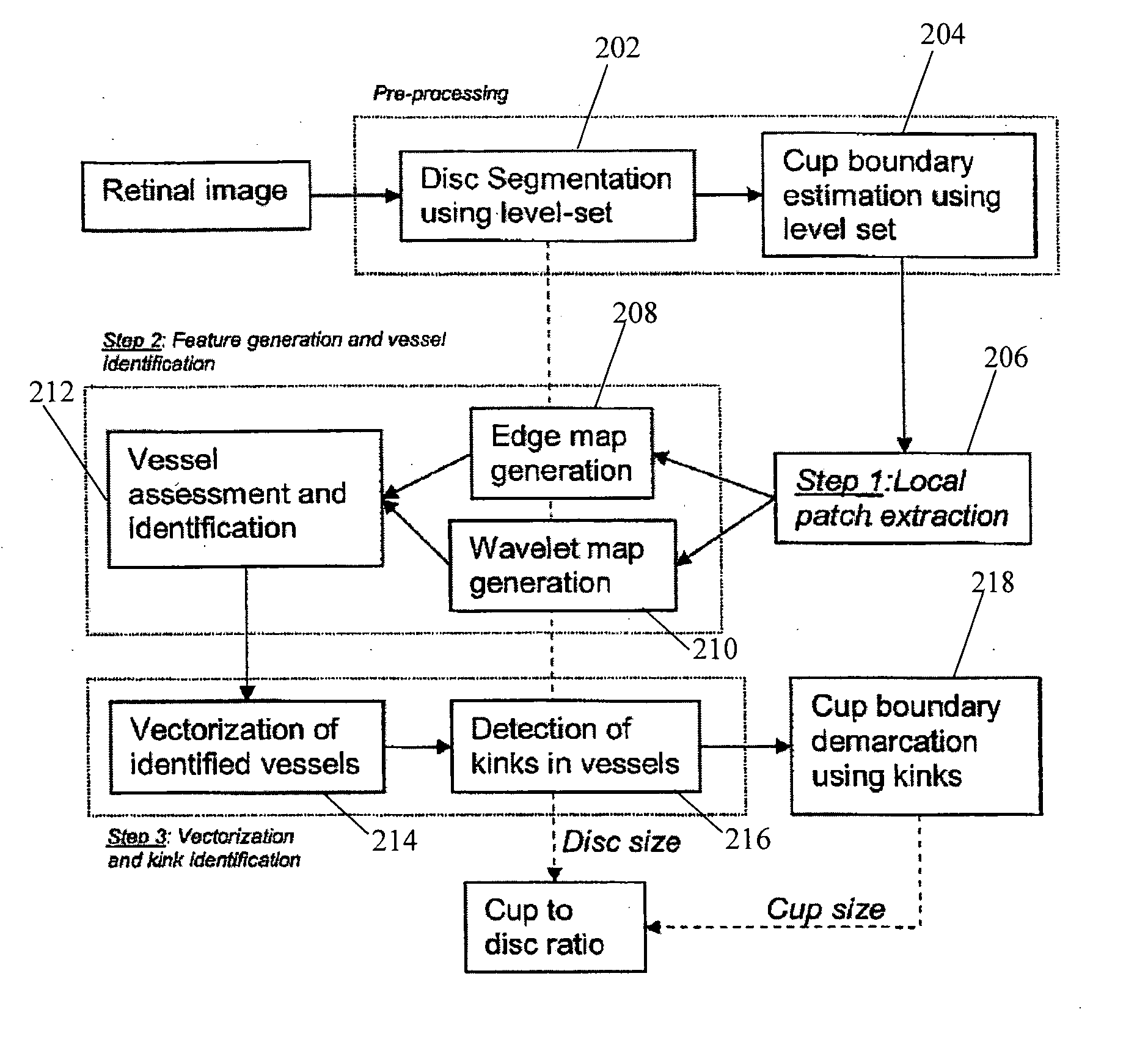
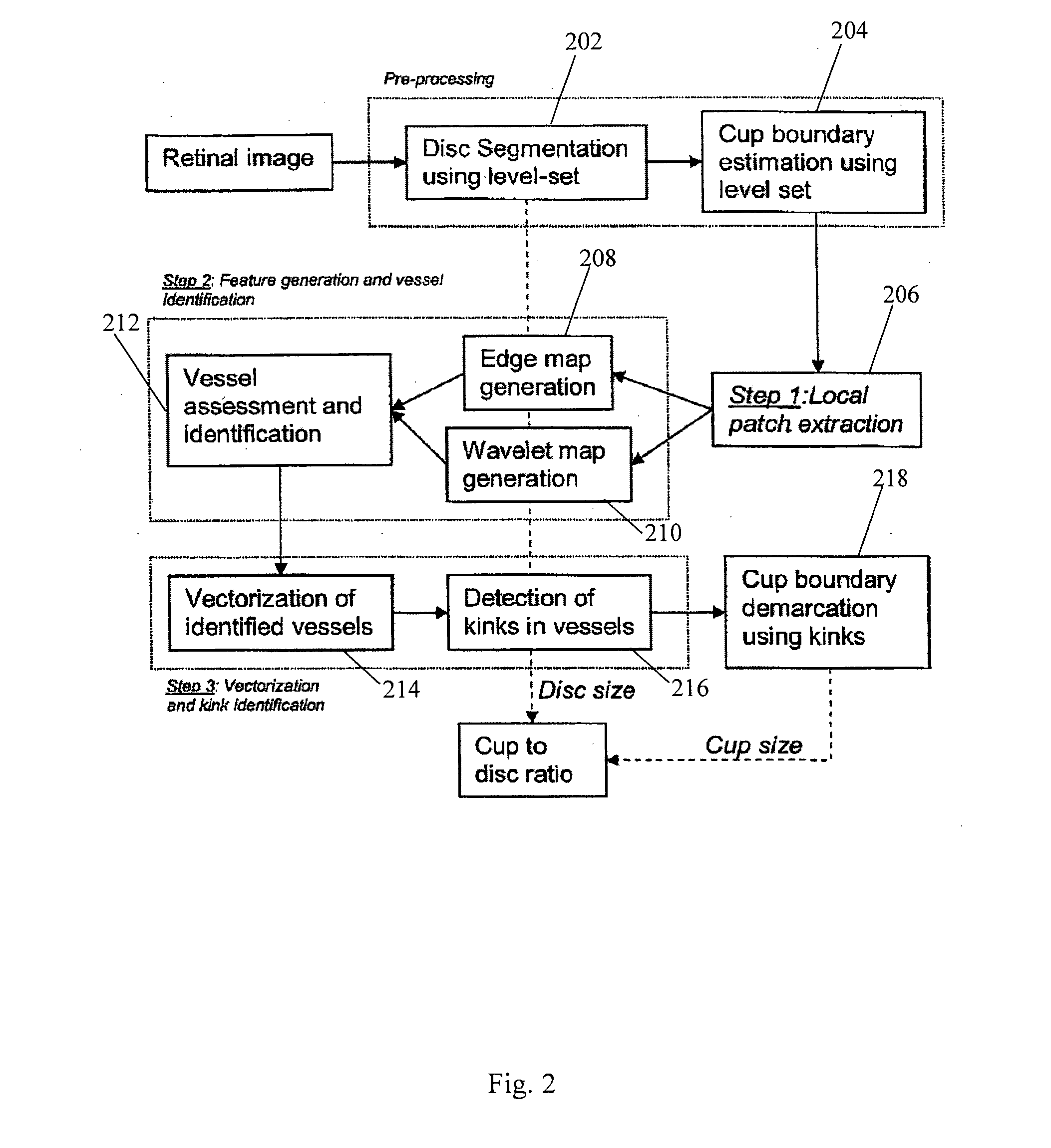
[0024]Referring to FIG. 2, the steps are illustrated of a method which is an embodiment of the present invention, and which determines the cup to disc ratio for the assessment of glaucoma using computerized kink detection.

[0025]The input to the embodiment is a single retinal image. Pre-processing involving steps 202 and 204 is first performed on the retinal image to obtain an estimate of the optic disc boundary on the image, and a preliminary estimate of the position of the cup boundary on the image. Next, local patch extraction (step 206) is performed on the preliminary estimate of the position of the cup boundary, the patches together defining a region proximate the preliminary estimate of the position of the cup boundary. This is followed by a process of “feature generation and vessel identification” involving steps 208, 210 (in which significant features on the patches are identified) and 212 (in which it is determined which of these features relate to blood vessel edges). The b...


PUM


Abstract

A method for determining the position of an optic cup boundary in a 2D retinal image. The method includes detecting kinks in blood vessels at an estimated boundary of the optic cup and the optic disc, and determining the position of the optic cup boundary in the 2D retinal image based on the detected kinks. The determined optic cup boundary may be used for determining a CDR which may in turn be used for determining a risk of contracting glaucomatous.

Description

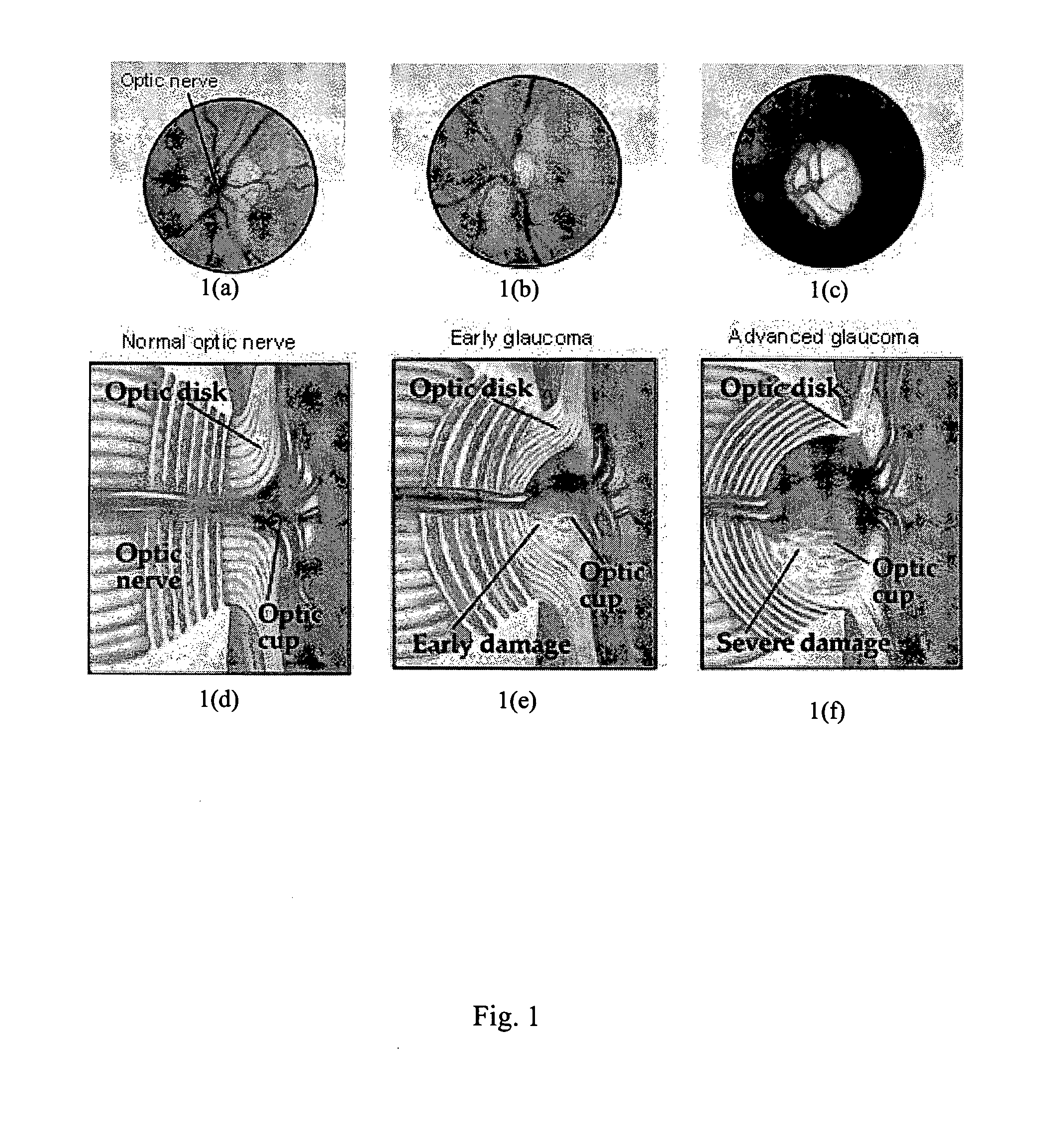
FIELD OF THE INVENTION[0001]The present invention relates to a method and system for determining an optic cup boundary in a 2D retinal image. The method and system can be used to determine a CDR which may in turn be used for determining a risk of contracting glaucoma.BACKGROUND OF THE INVENTION[0002]Glaucoma is one of the leading causes of blindness worldwide. According to a World Health Organization report in 2004 [1], glaucoma is the second leading cause of blindness, with 12.3% of visual impairment globally being attributed to this disease. It has been estimated that more than half of the 70 million glaucoma cases are in Asia [2]. In Singapore, a recent community-based study [3] found that 3.2% of Chinese respondents over the age of 40 were found to have glaucoma. Furthermore, the disease is closely associated with age [4] and according to the Glaucoma Research Foundation [5], a person over the age of 60 is “six times more likely to get glaucoma”. Given the rapidly aging populati...

Claims


Application Information

Patent Timeline
IPC IPC(8): G06K9/00
CPCA61B3/12G06T2207/30041G06T2207/20161G06T7/0083G06T7/12
Inventor WONG, WING KEE DAMONLIU, JINGLIM, JOON HWEELI, HUIQITAN, NGAN MENGWONG, TIEN YIN
Owner SINGAPORE HEALTH SERVICES PTE
Learn More