Image coding apparatus

Active Publication Date: 2011-10-06
MAXELL HLDG LTD
View PDF6 Cites 12 Cited by
  • Summary
  • Abstract
  • Description
  • Claims
  • Application Information

AI Technical Summary

Benefits of technology

[0007]According to the present invention, it becomes possible to provide the image coding apparatus which makes it possible to suppre

Problems solved by technology

No consideration, however, has been given to a case where the Intra-frame coding is used in an environment such as wireless transmis

Method used


Image

  • Image coding apparatus
  • Image coding apparatus
  • Image coding apparatus

Examples


Embodiment Construction

[0019]Hereinafter, the explanation will be given below concerning the coding scheme in a manner where the H. 264 coding, i.e., the international standardization scheme for the video-image coding, is selected as its example.

[0020]FIG. 3 is a diagram for illustrating a configuration example of the image coding apparatus.

[0021]The image coding apparatus includes the following configuration components: An Intra-prediction unit 303 for making the Intra prediction about an inputted image inputted from an image input unit 301, an Inter-prediction unit 304 for making the Inter prediction thereabout, a judgment unit 305 for making a judgment as to whether the prediction is the Intra prediction or the Inter prediction, a difference image unit 306 for generating an error image by assuming the difference between the inputted image and the prediction image judged by the judgment unit 305, a DCT / quantization unit 307 for performing the DCT / quantization with respect to the error image, a stream ge...


PUM


Abstract

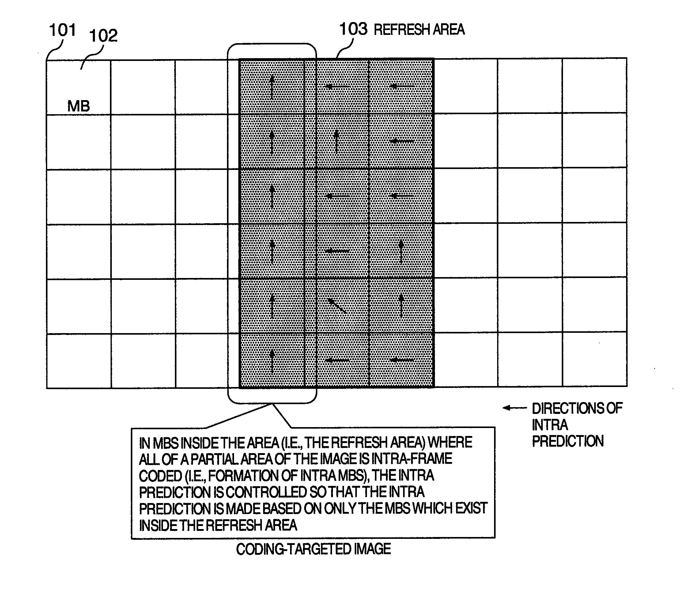
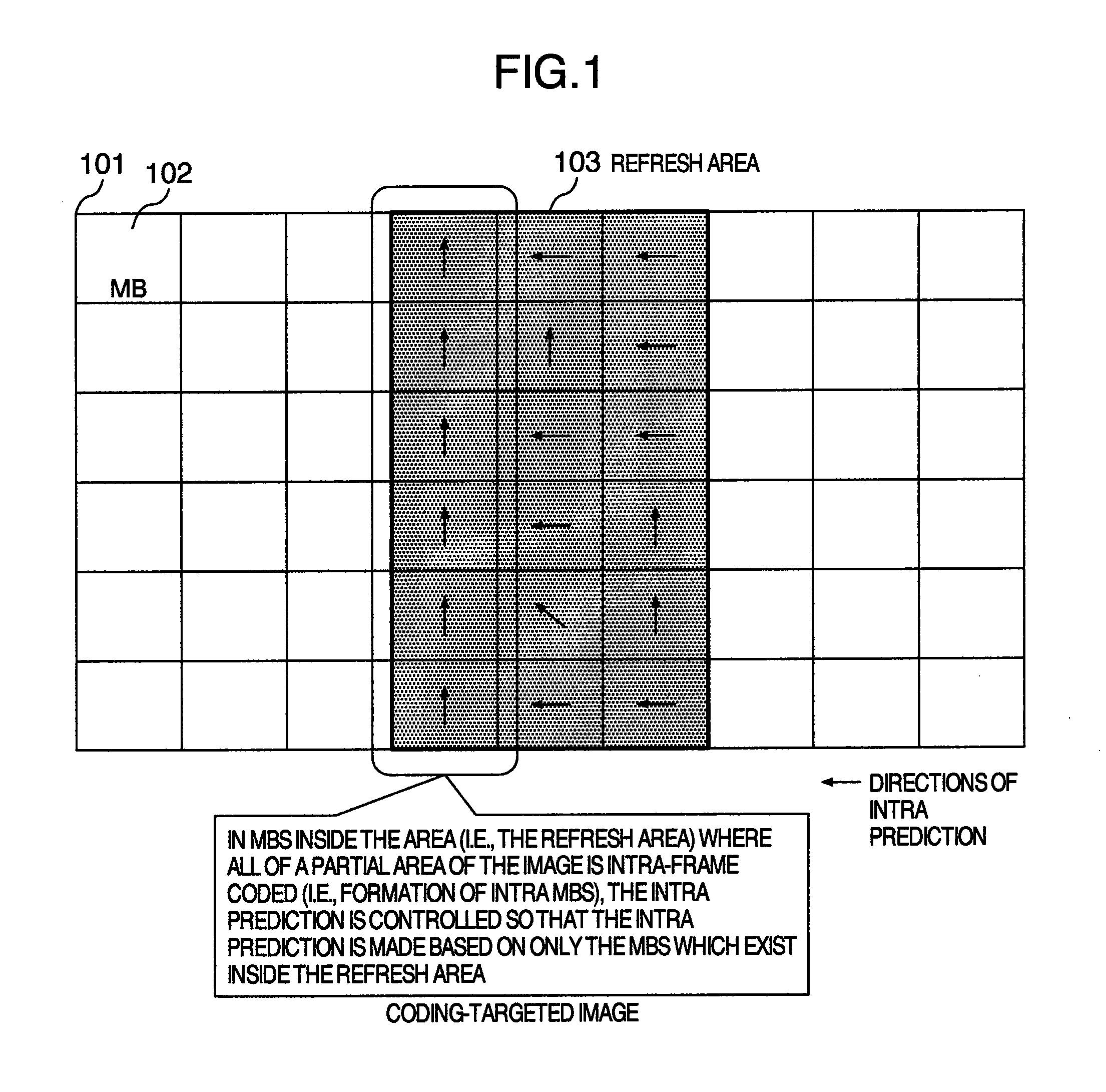
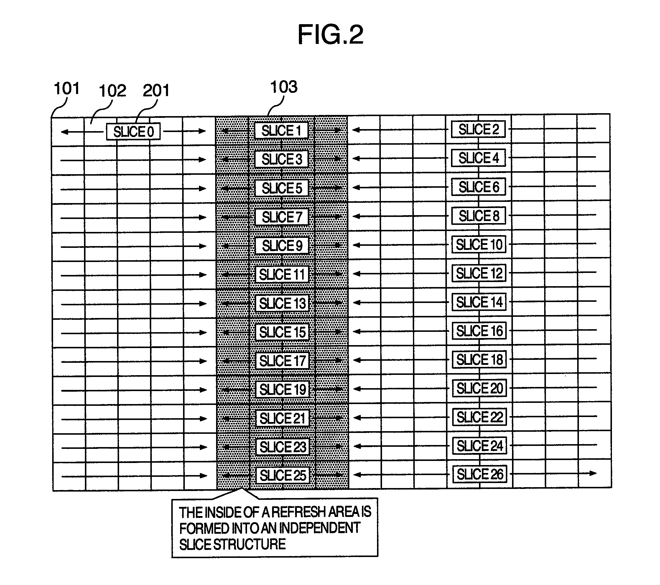
A refresh area is taken advantage of when a series of images are coded using Intra-frame coding and Inter-frame coding, a partial area of an image being forcefully Intra-frame coded (Intra MBs) in the refresh area. As the prediction mode for prediction of the Intra MBs inside the refresh area, a prediction mode is selected where the prediction is executable based on only the image that exists inside the refresh area.

Description

INCORPORATION BY REFERENCE[0001]The present application claims priority from Japanese application JP 2010-080105 filed on Mar. 31, 2010, the content of which is hereby incorporated by reference into this application.BACKGROUND OF THE INVENTION[0002]The present invention relates to an image coding apparatus and method which allows an image to be transferred with a low delay.[0003]In JP-A-6-110831, the disclosure has been made concerning a data transfer apparatus for performing the data-packet transfer between communications modules via a serial bus. Moreover, an object of this data transfer apparatus is to make the higher-speed transfer capability available even in a case where the signal-line number and clock rate are the same as the bus width of the serial transfer.SUMMARY OF THE INVENTION[0004]In order to code an image, and to transfer the coded image with a low delay, the proposal has been also made concerning a scheme for using the Intra-frame coding forcefully with respect to a...

Claims


Application Information

Patent Timeline
IPC IPC(8): G06K9/36H03M7/36H04N19/50H04N19/11H04N19/167H04N19/176H04N19/189H04N19/503H04N19/593H04N19/65
CPCH04N19/61H04N19/895H04N19/174H04N19/107
Inventor YATABE, YUSUKEKOMI, HIRONORIOKADA, MITSUHIROMYOJIN, TOMOYUKIMIZOSOE, HIROKI
Owner MAXELL HLDG LTD
Why Eureka
Try Eureka