

Metal Bonding Member and Fabrication Method of the Same
- Summary
- Abstract
- Description
- Claims
- Application Information
AI Technical Summary
Benefits of technology
Problems solved by technology
Method used
Image

Examples
first embodiment
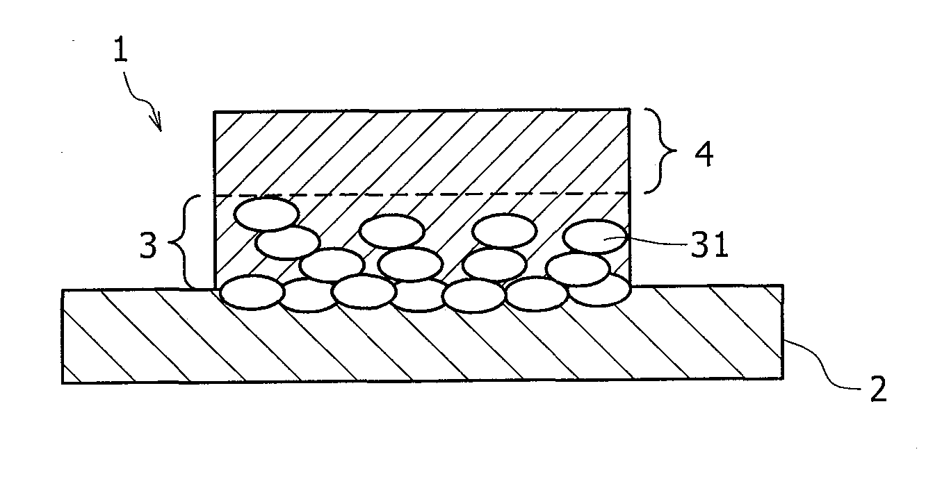
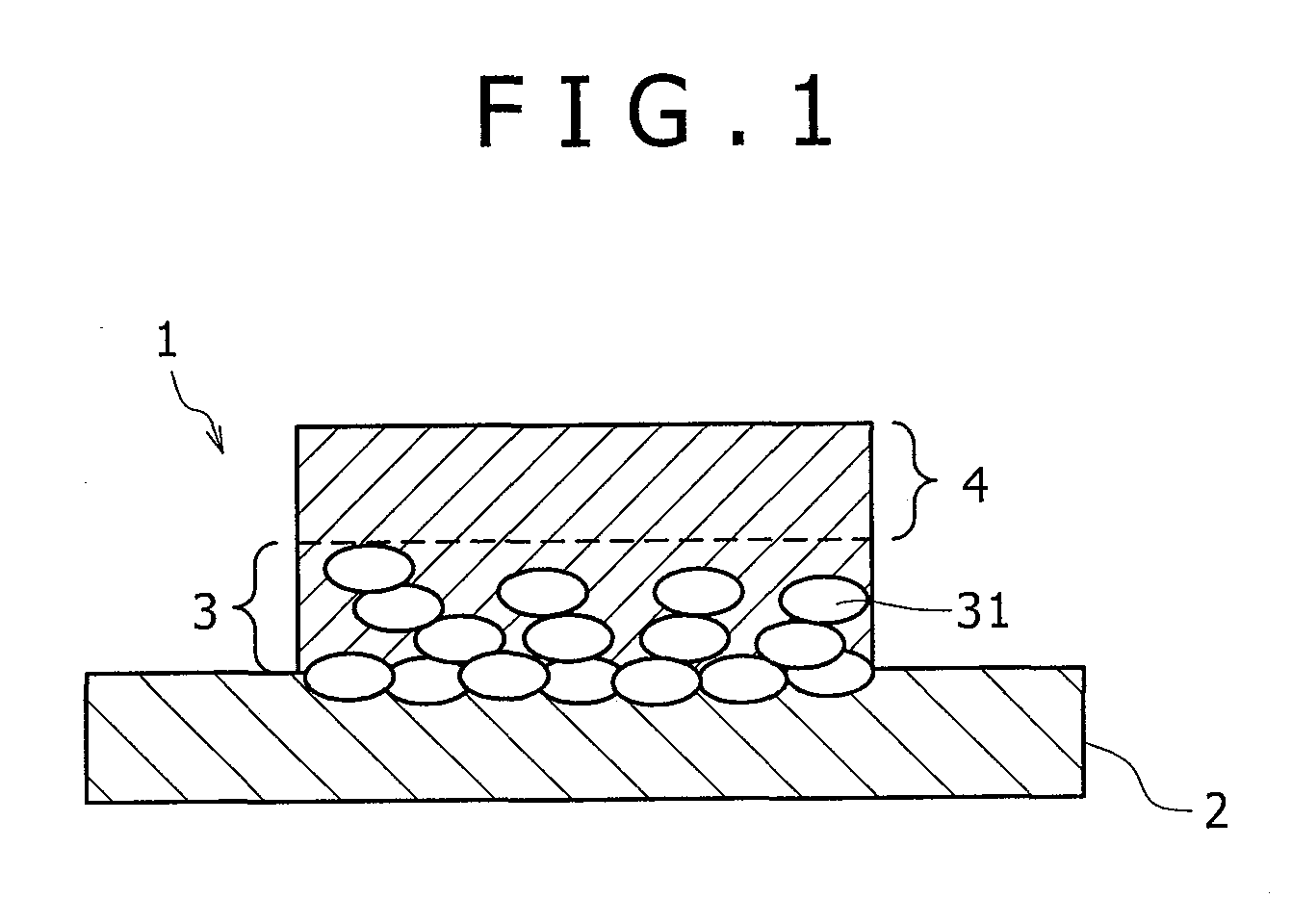
[0020]a metal bonding member according to the present invention will be described with reference to FIG. 1.
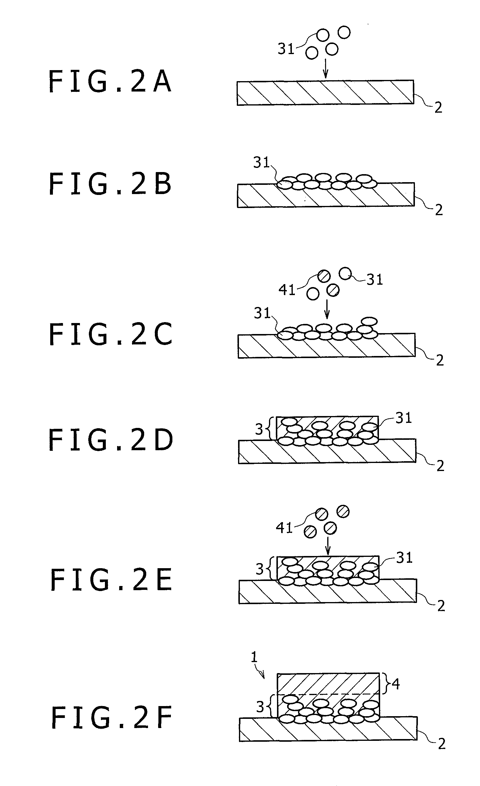
[0021]A metal bonding member 1 of this embodiment is formed to have a plate-shaped metal substrate 2 made of Al, an adhesion layer 3 formed on the metal substrate 2, the adhesion layer 3 including a plurality of Cu adhesion particles 31 partially buried in the metal substrate 2 and a Sn—Cu solder phase, and an Sn—Cu solder layer 4 formed on the adhesion layer 3.
[0022]Now, as shown in FIG. 1, in the adhesion layer 3, the plurality of Cu adhesion particles 31 are deposited on the surface bonded to the metal substrate 2, and the plurality of Cu particles are partially buried in the metal substrate 2 in the interface therebetween. On this account, an excellent adhesion strength can be obtained between the adhesion layer 3 and the metal substrate 2 due to anchor effect. Further, because the adhesion layer 3 has the solder phase on the surface to be bonded to the solder layer 4, an e...
second embodiment
[0034]A metal bonding member 1′ is configured to include a plate-shaped metal substrate 2 made of Al, an adhesion layer 3′ formed on the metal substrate 2, the adhesion layer 3′ including a plurality of Cu adhesion particles 31 partially buried in the metal substrate 2, and an Sn—Cu solder layer 4 formed on the adhesion layer 3′.
[0035]The difference between the second embodiment and the first embodiment is in that the adhesion layer 3 is formed only of Cu particles. Accordingly, the interfaces of the plurality of Cu particles forming the adhesion layer 3 do not form in uneven shapes as in the first embodiment, and the adhesion strength and the temperature cycling reliability as those in the first embodiment are not obtained. However, as described later, according to this embodiment, because it is unnecessary to use particle impaction deposition for forming the solder layer 4, versatility is increased since broader options are available for the materials of the solder layer 4.
[0036]...
PUM
| Property | Measurement | Unit |
|---|---|---|
| Adhesion strength | aaaaa | aaaaa |
Abstract
Description
Claims
Application Information