
Method for producing group iii nitride semiconductor light-emitting device

a technology of nitride semiconductor and light-emitting device, which is applied in the manufacture of semiconductor/solid-state devices, semiconductor devices, electrical devices, etc., can solve the problems of non-polar plane surface, reduced emission performance and crystallinity degradation, and the nitride semiconductor layer is not readily wet-etched, so as to improve light extraction performance

Inactive Publication Date: 2011-10-06
TOYODA GOSEI CO LTD
View PDF1 Cites 20 Cited by
  • Summary
  • Abstract
  • Description
  • Claims
  • Application Information

AI Technical Summary

Benefits of technology

[0009]In view of the foregoing, an object of the present invention is to improve the light extraction performance of a Group III nitride semiconductor light-emitting device whose main surface is a plane which provides an internal electric field of zero.

Problems solved by technology

In such light-emitting devices, an internal electric field is generated in semiconductor crystals due to piezopolarization, which may cause problems, including reduction of emission performance and deterioration of crystallinity.
Conceivably, the Group III nitride semiconductor layer employed has a c-plane main surface, although Japanese Patent Application Laid-Open (kokai) No. 2007-36240 does not particularly disclose the crystal orientation of the semiconductor layer.
However, a non-polar plane surface (e.g., m-plane or a-plane surface) of a Group III nitride semiconductor layer is not readily wet-etched, since such a surface exhibits resistance to a strong alkaline solution.
In addition, formation of an embossment through dry etching is not desirable, since dry etching may cause damage to crystals.

Method used


Image

  • Method for producing group iii nitride semiconductor light-emitting device
  • Method for producing group iii nitride semiconductor light-emitting device
  • Method for producing group iii nitride semiconductor light-emitting device

Examples


embodiment 2

[0057]FIG. 3 shows the configuration of a light-emitting device 2 according to Embodiment 2. As shown in FIG. 3, the light-emitting device 2 includes a support substrate 10; a metal layer 11 formed on the support substrate 10; a p-electrode 12 bonded to the support substrate 10 via the metal layer 11; a p-type layer 103, a light-emitting layer 104, and an n-type layer 105, which are formed of a Group III nitride semiconductor and sequentially stacked on the p-electrode 12; and an n-electrode 16 formed on the n-type layer 105. The light-emitting device 2 has the same configuration as the light-emitting device 1 according to Embodiment 1, except for the p-type layer 103, the light-emitting layer 104, and the n-type layer 105.

[0058]Each of the p-type layer 103, the light-emitting layer 104, and the n-type layer 105 is formed of a Group III nitride semiconductor layer having a (11-22)-plane main surface. The (11-22)-plane surface is inclined by about 60° with respect to c-plane, and pro...


PUM

PropertyMeasurementUnit
semiconductoraaaaaaaaaa
internal electric field intensityaaaaaaaaaa
crystallinityaaaaaaaaaa

Abstract

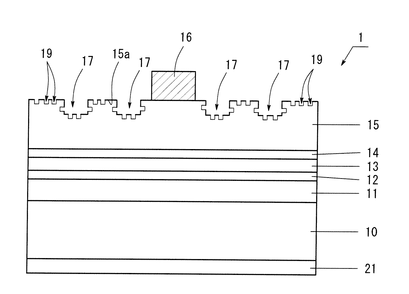
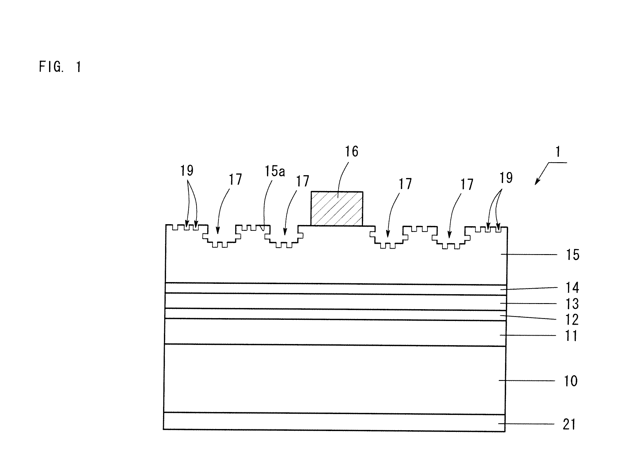
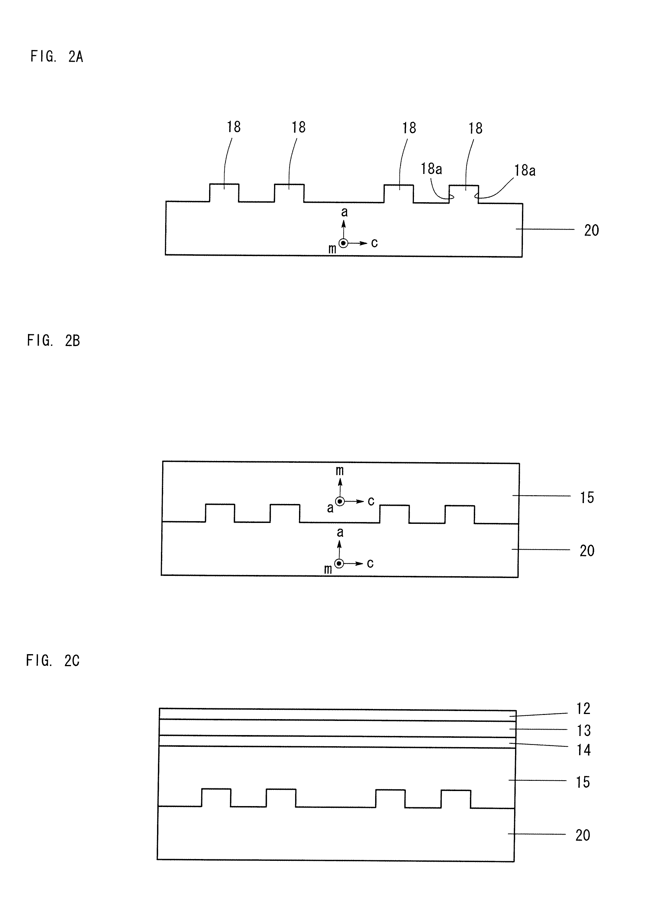
The present invention provides a method for producing a Group III nitride semiconductor light-emitting device whose main surface is a plane that provides an internal electric field of zero, and which exhibits improved light extraction performance. In the production method, one surface of an a-plane sapphire substrate is subjected to dry etching, to thereby form an embossment pattern having a plurality of mesas which are arranged in a honeycomb-dot pattern as viewed from above; and an n-type layer, a light-emitting layer, and a p-type layer, each of which is formed of a Group III nitride semiconductor layer having an m-plane main surface, are sequentially stacked on the surface of the sapphire substrate on which the mesas are formed. Subsequently, a p-electrode is formed on the p-type layer, and the p-electrode is bonded to a support substrate via a metal layer. Next, the sapphire substrate is removed through the laser lift-off process. On the thus-exposed surface of the n-type layer is formed an embossment pattern having dents provided through transfer of the mesas of the embossment pattern of the sapphire substrate. Then, the emboss-patterned surface of the n-type layer is subjected to wet etching, to thereby form numerous etched pits.

Description

BACKGROUND OF THE INVENTION[0001]1. Field of the Invention[0002]The present invention relates to a method for producing a Group III nitride semiconductor light-emitting device whose main surface is a plane which provides an internal electric field intensity of 10% or less that of a Group III nitride semiconductor layer having a c-plane main surface, and more particularly to a method for producing a Group III nitride semiconductor light-emitting device exhibiting improved light extraction performance.[0003]2. Background Art[0004]Hitherto, Group III nitride semiconductor light-emitting devices are generally produced from a Group III nitride semiconductor layer having a c-plane main surface. In such light-emitting devices, an internal electric field is generated in semiconductor crystals due to piezopolarization, which may cause problems, including reduction of emission performance and deterioration of crystallinity. Thus, in recent years, attempts have been made to produce a Group III...

Claims


Application Information

Patent Timeline
Patent Type & Authority Applications(United States)
IPC IPC(8): H01L33/22
CPCH01L33/007H01L33/20H01L33/0079H01L33/0093
Inventor SAITO, YOSHIKIOKUNO, KOJIUSHIDA, YASUHISA
Owner TOYODA GOSEI CO LTD
Learn More