
Group III nitride semiconductor light-emitting device and production method therefor

a technology of nitride semiconductor and light-emitting device, which is applied in the direction of semiconductor/solid-state device manufacturing, semiconductor devices, electrical apparatus, etc., can solve the problems of layer reducing light extraction performance, variation in brightness or light distribution, etc., to improve light extraction performance, and improve light extraction performance

Inactive Publication Date: 2009-08-13
TOYODA GOSEI CO LTD
View PDF10 Cites 21 Cited by
  • Summary
  • Abstract
  • Description
  • Claims
  • Application Information

AI Technical Summary

Benefits of technology

[0007]In view of the foregoing, an object of the present invention is to provide a method for producing a Group III nitride semiconductor light-emitting device, which method facilitates tapering of a bottom portion of a growth substrate at high reproducibility. Another object of the present invention is to provide a Group III nitride semiconductor light-emitting device including a bottom-tapered growth substrate.

Problems solved by technology

In a method disclosed in Japanese Patent Application Laid-Open (kokai) No. 2005-302804, a damaged layer formed by such a machining process is removed through dry etching, since the damaged layer reduces light extraction performance.
However, the method disclosed in Japanese Patent Application Laid-Open (kokai) No. 2005-302804 poses a problem in terms of ease of processing, since the method requires two steps (machining and dry etching) for forming a bottom-tapered GaN substrate.
Meanwhile, when a tapered substrate is formed through a machining process such as dicing, poor reproducibility in tapering may cause variation in brightness or light distribution.

Method used


Image

  • Group III nitride semiconductor light-emitting device and production method therefor
  • Group III nitride semiconductor light-emitting device and production method therefor
  • Group III nitride semiconductor light-emitting device and production method therefor

Examples


embodiment 1

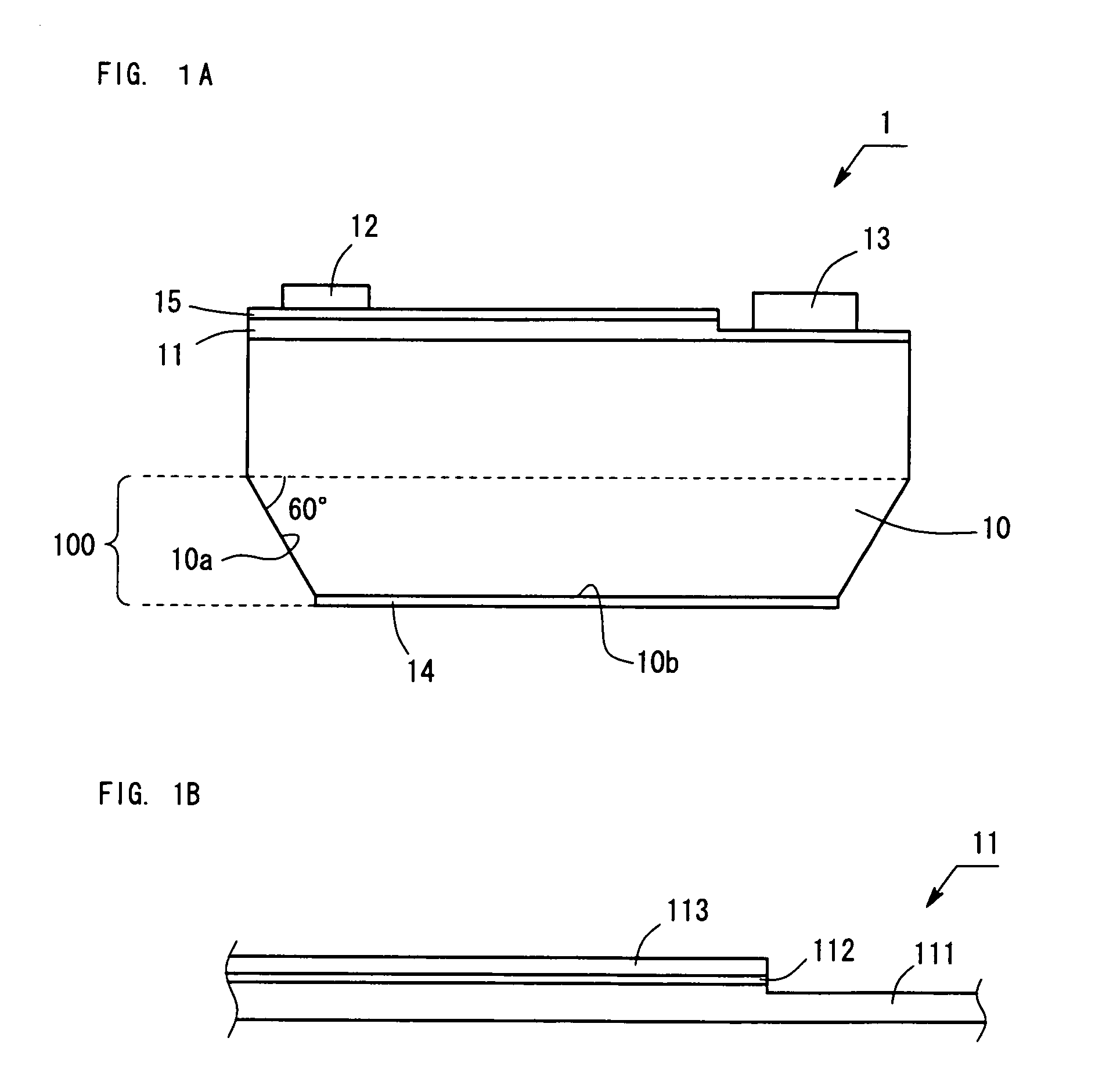
[0095]FIG. 1 shows the structure of a face-up-type light-emitting device 1 according to Embodiment 1. The light-emitting device 1 has a size of about 350 μm×about 350 μm.

[0096]The structure of the light-emitting device 1 will now be described. As shown in FIG. 1A, the light-emitting device 1 includes a GaN substrate 10 serving as a growth substrate; a Group III nitride semiconductor layer 11 formed on the top surface of the GaN substrate 10; an ITO electrode 15 formed on the top surface of the semiconductor layer 11; a p-electrode 12; an n-electrode 13; and an SiO2 mask 14 formed on the bottom surface 10b of the GaN substrate 10.

[0097]As shown in FIG. 1B, the semiconductor layer 11 has a structure in which an n-layer 111, an active layer 112, and a p-layer 113 are sequentially stacked. The n-layer 111 has a structure in which an n-type GaN contact layer doped with Si at high concentration and a GaN n-cladding layer are sequentially stacked. The p-layer 113 has a structure in which a...

embodiment 2

[0112]FIG. 3 shows the structure of a face-down-type light-emitting device 2 according to Embodiment 2. The light-emitting device 2 has a structure including a GaN substrate 20, a semiconductor layer 11 formed on the top surface of the substrate 20, a highly reflective Ag electrode 25, a p-electrode 12, and an n-electrode 13. As in the case of the light-emitting device 1 according to Embodiment 1, the light-emitting device 2 has a size of about 350 μm×about 350 μm. The main difference between the light-emitting device 2 and the light-emitting device 1 is attributed to the difference in form between the processed GaN substrate 20 and the processed GaN substrate 10.

[0113]The GaN substrate 20 is a C-plane substrate having a thickness of 185 μm, and the bottom surface of the substrate is an N-polar surface. The GaN substrate 20 has an absorption coefficient of 3 / cm or less with respect to the wavelength of light emitted from the light-emitting device 2. The bottom surface 20b of the GaN...

embodiment 3

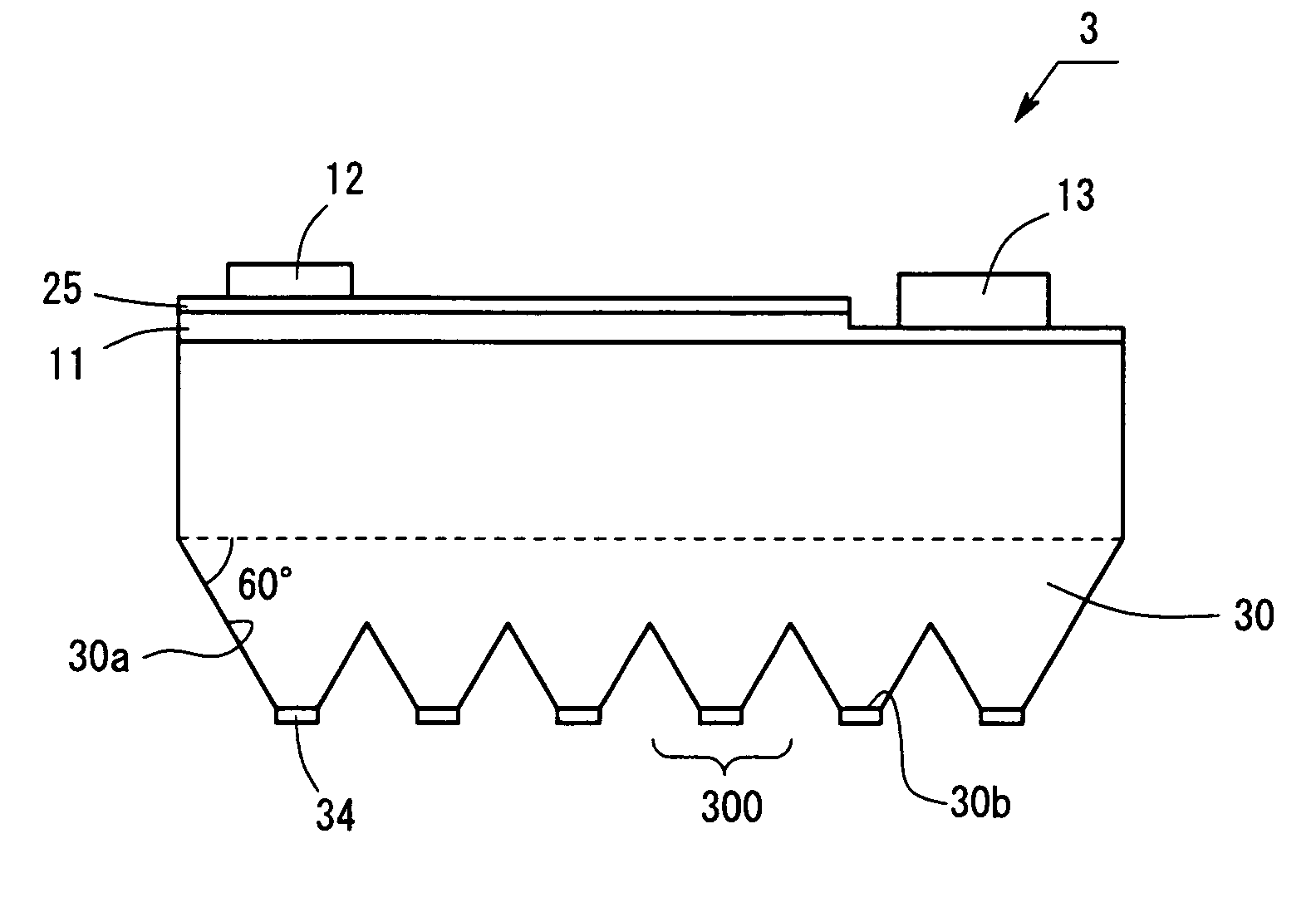
[0119]FIG. 5 shows the structure of a light-emitting device 3 according to Embodiment 3. Similar to the case of the light-emitting device 2 according to Embodiment 2, the light-emitting device 3 has a structure including a GaN substrate 30, a semiconductor layer 11 formed on the top surface of the substrate 30, a highly reflective electrode 25, a p-electrode 12, and an n-electrode 13. As in the case of the light-emitting device 2 according to Embodiment 2, the light-emitting device 3 has a size of about 350 μm×about 350 μm. The main difference between the light-emitting device 3 and the light-emitting device 2 is attributed to the difference in form between the processed GaN substrate 30 and the processed GaN substrate 20.

[0120]The GaN substrate 30 is a C-plane substrate having a thickness of 185 μm, and the bottom surface of the substrate is an N-polar surface. The GaN substrate 30 has an absorption coefficient of 3 / cm or less with respect to the wavelength of light emitted from th...


PUM

PropertyMeasurementUnit
depthaaaaaaaaaa
depthaaaaaaaaaa
depthaaaaaaaaaa

Abstract

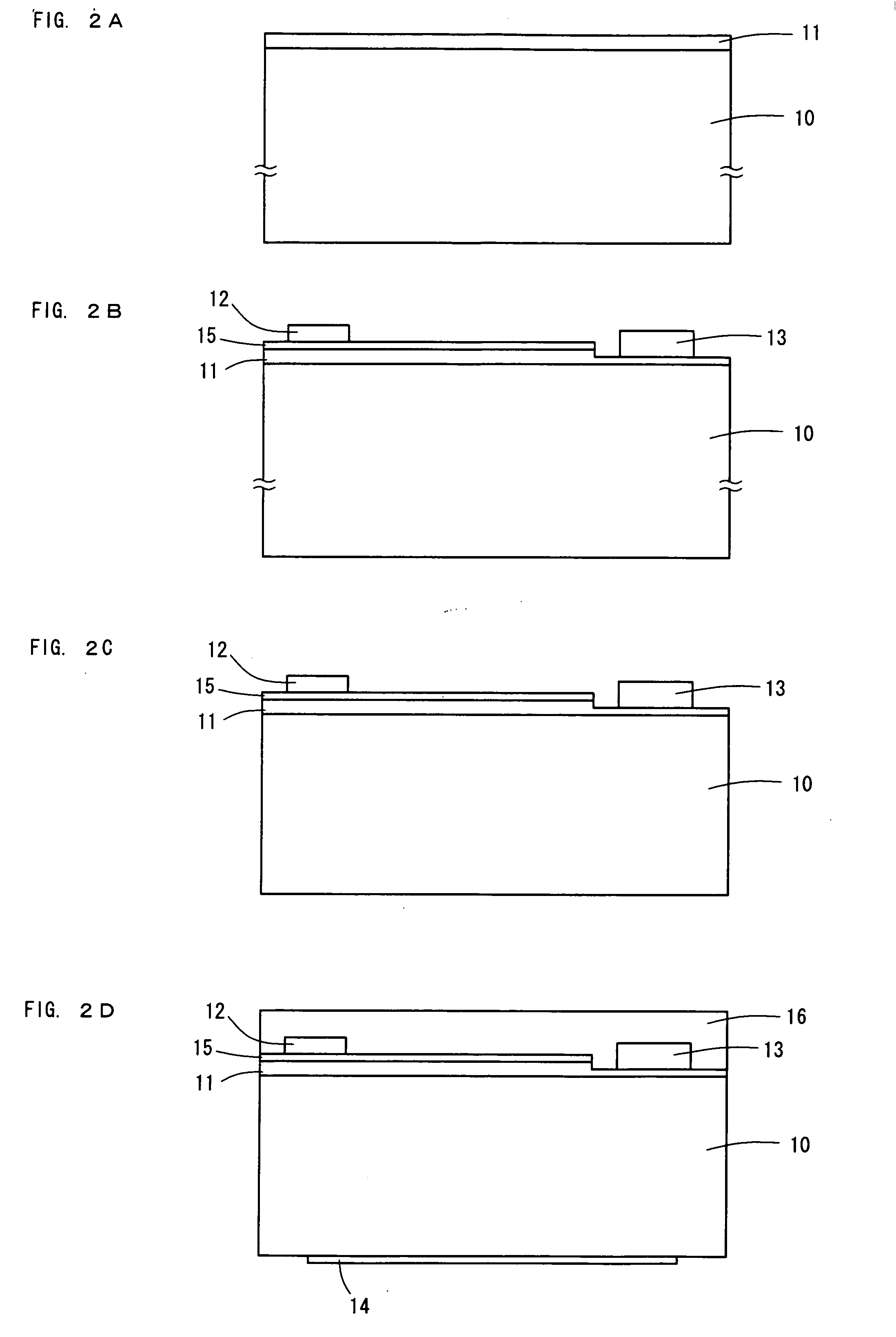
Provided is a method for producing a Group III nitride semiconductor light-emitting device including a GaN substrate serving as a growth substrate, which method facilitates tapering of a bottom portion of the GaN substrate. In the production method, firstly, a Group III nitride semiconductor layer, an ITO electrode, a p-electrode, and an n-electrode are formed on the top surface of a GaN substrate through MOCVD. Thereafter, the GaN substrate is thinned through mechanical polishing of the bottom surface thereof, and then scratches formed by mechanical polishing are removed through chemical mechanical polishing, to thereby planarize the bottom surface. Subsequently, a mask is formed on the bottom surface of the GaN substrate, followed by wet etching with phosphoric acid. By virtue of anisotropy in etching of GaN with phosphoric acid, a tapered surface is exposed so as to be inclined by about 60° with respect to the GaN substrate.

Description

BACKGROUND OF THE INVENTION[0001]1. Field of the Invention[0002]The present invention relates to a Group III nitride semiconductor light-emitting device including a growth substrate formed from a Group III nitride semiconductor (hereinafter may be referred to as “Group III nitride semiconductor growth substrate”), and to a method for producing the light-emitting device. More particularly, the present invention relates to a light-emitting device exhibiting improved light extraction performance, and to a method for producing the light-emitting device.[0003]2. Background Art[0004]Hitherto, there has been known a Group III nitride semiconductor light-emitting devices having a GaN growth substrate, in which the bottom portion of the GaN substrate is processed to have a tapered form for improving the light extraction performance of the light-emitting device (see Japanese Patent Application Laid-Open (kokai) Nos. H11-317546, 2003-086838, and 2005-302804).[0005]Such a bottom-tapered GaN sub...

Claims


Application Information

Patent Timeline
Patent Type & Authority Applications(United States)
IPC IPC(8): H01L33/00H01L33/32H01L33/62
CPCH01L21/30617H01L33/32H01L33/20
Inventor GOSHONOO, KOICHIMORIYAMA, MIKI
Owner TOYODA GOSEI CO LTD
Learn More