
Apparatus and method for lowering intraocular pressure in an eye

a technology of intraocular pressure and applicator, which is applied in the field of applicator and corneal implant, can solve the problems of damage to the optic nerve, severe damage to the eye, and loss of sight in humans, and achieve the effect of preventing harmful intraocular pressur

Inactive Publication Date: 2011-10-06
SUNALP MURAD A
View PDF8 Cites 30 Cited by
  • Summary
  • Abstract
  • Description
  • Claims
  • Application Information

AI Technical Summary

Benefits of technology

"The invention is a device that helps to prevent harmful intraocular pressure in the eye by actively evacuating aqueous fluid from the anterior chamber of the eye. It is powered by a photovoltaic cell and uses a nanopump to continuously remove fluid. The device can be implanted in the eye and is controlled by a data processor to adjust the flow of fluid and keep intraocular pressure safe. The device can also be activated by a pressure sensor in the eye or when the photovoltaic cell reaches a predetermined energy level. Overall, the invention provides a means to prevent harmful intraocular pressure and maintain eye health."

Problems solved by technology

High intraocular pressure caused by a build up of aqueous fluid which accompanies Glaucoma is one of the main causes of damage to the optic nerve.
Thus, the high pressure can be a major cause of sight loss in humans.
When a patient suffers from a rapid rise in such pressure or a frequent and long term rise in ocular pressure that can easily reach a dangerously high point, severe damage to the eye and permanent loss of sight can result.
Unfortunately, following a period of time after the procedure the incisions heal and scar, causing the pressure to rise once again and risk the loss of sight in the patient.
The device simply provides a passive means for drainage of fluid from the anterior chamber of the eye and by no means provides active evacuation of such fluid.
Nordquist also lacks the provision of direct communication between the anterior chamber and the exterior region of the eye which may increase the risk of infection to the anterior chamber.
Consequently, in patients with varying fluid pressure increases, or those with long term increases, the passive tube may lack the ability to communicate sufficient fluid volume to protect the patient.

Method used


Image

  • Apparatus and method for lowering intraocular pressure in an eye
  • Apparatus and method for lowering intraocular pressure in an eye
  • Apparatus and method for lowering intraocular pressure in an eye

Examples


Embodiment Construction

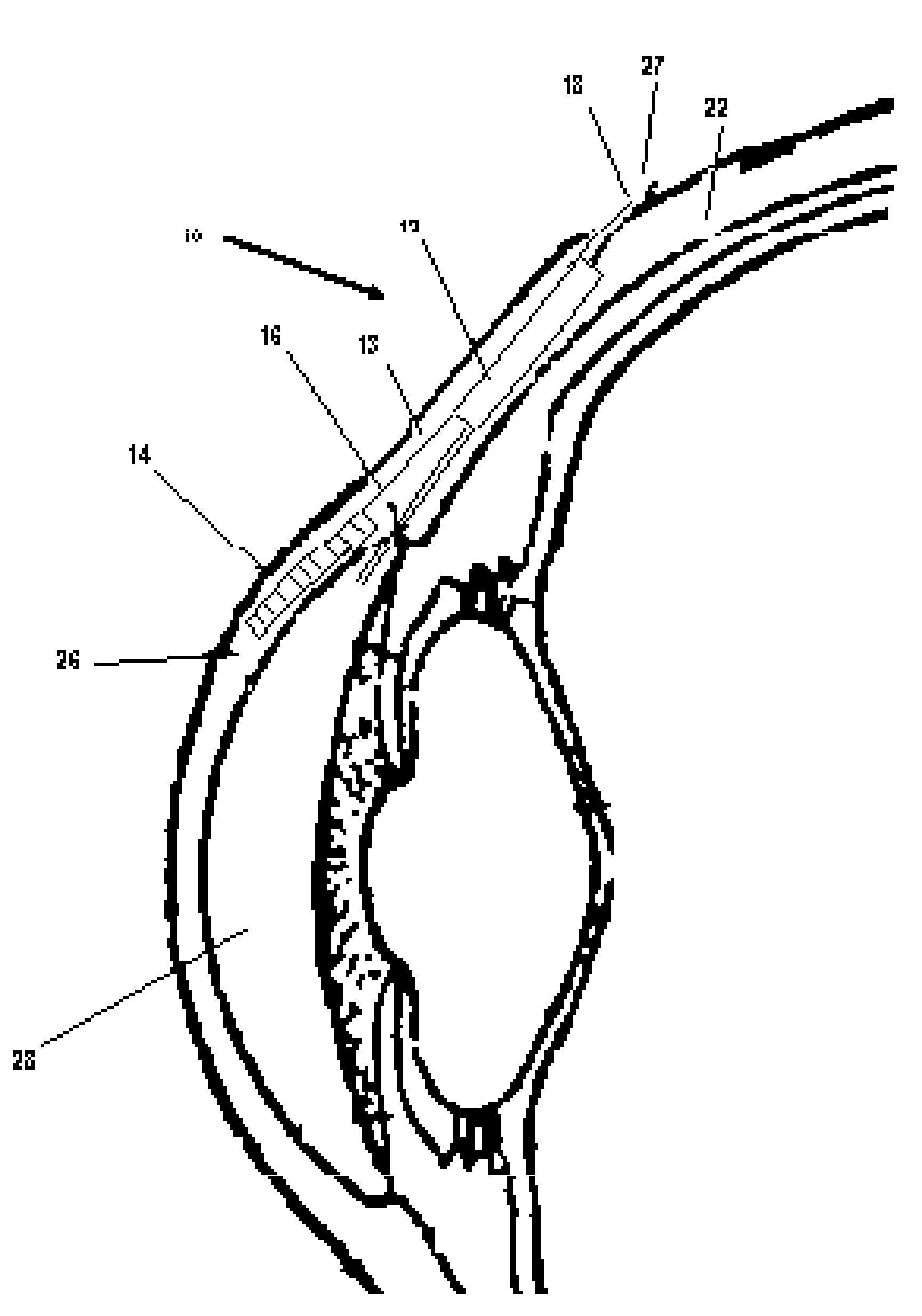
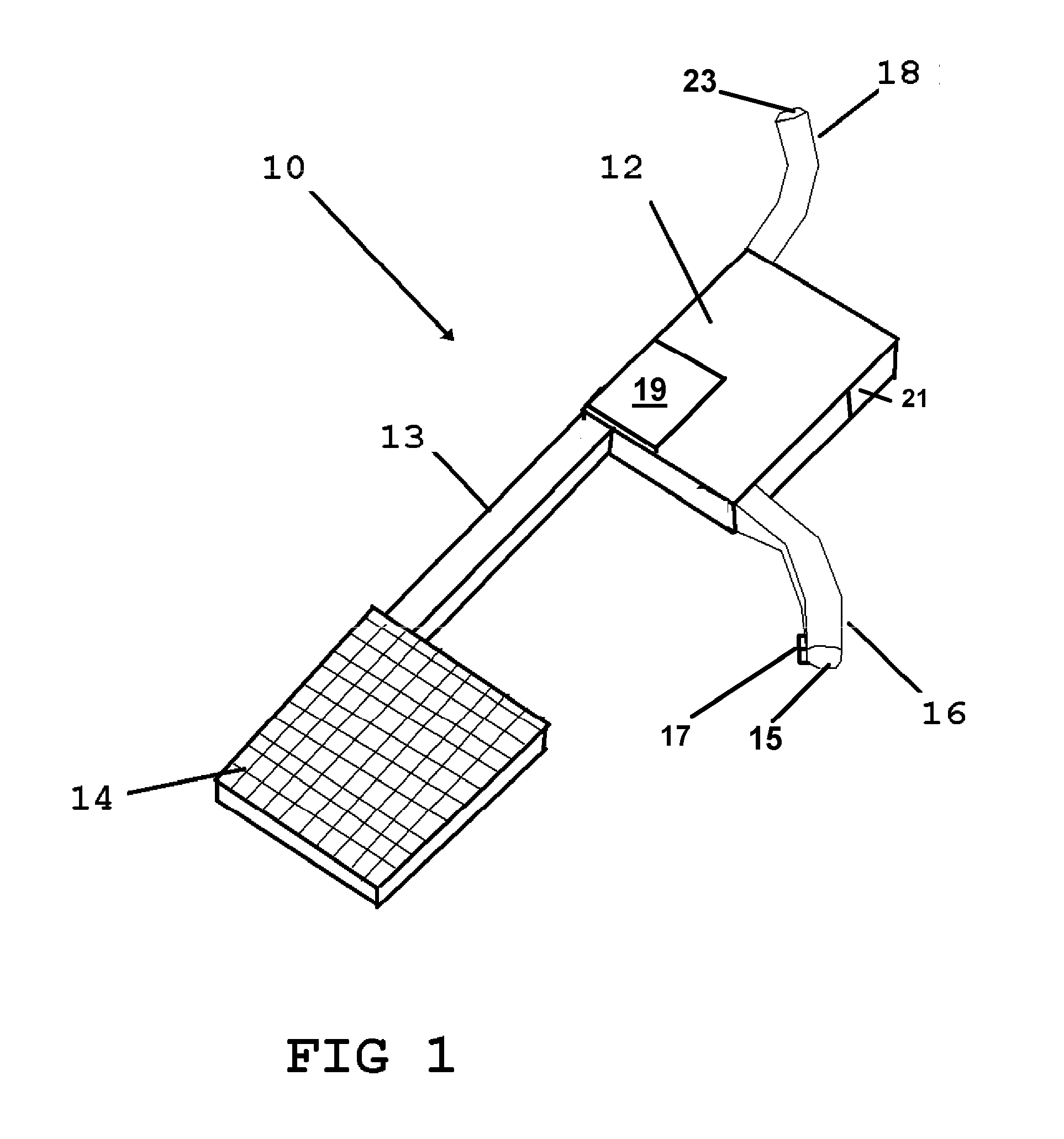
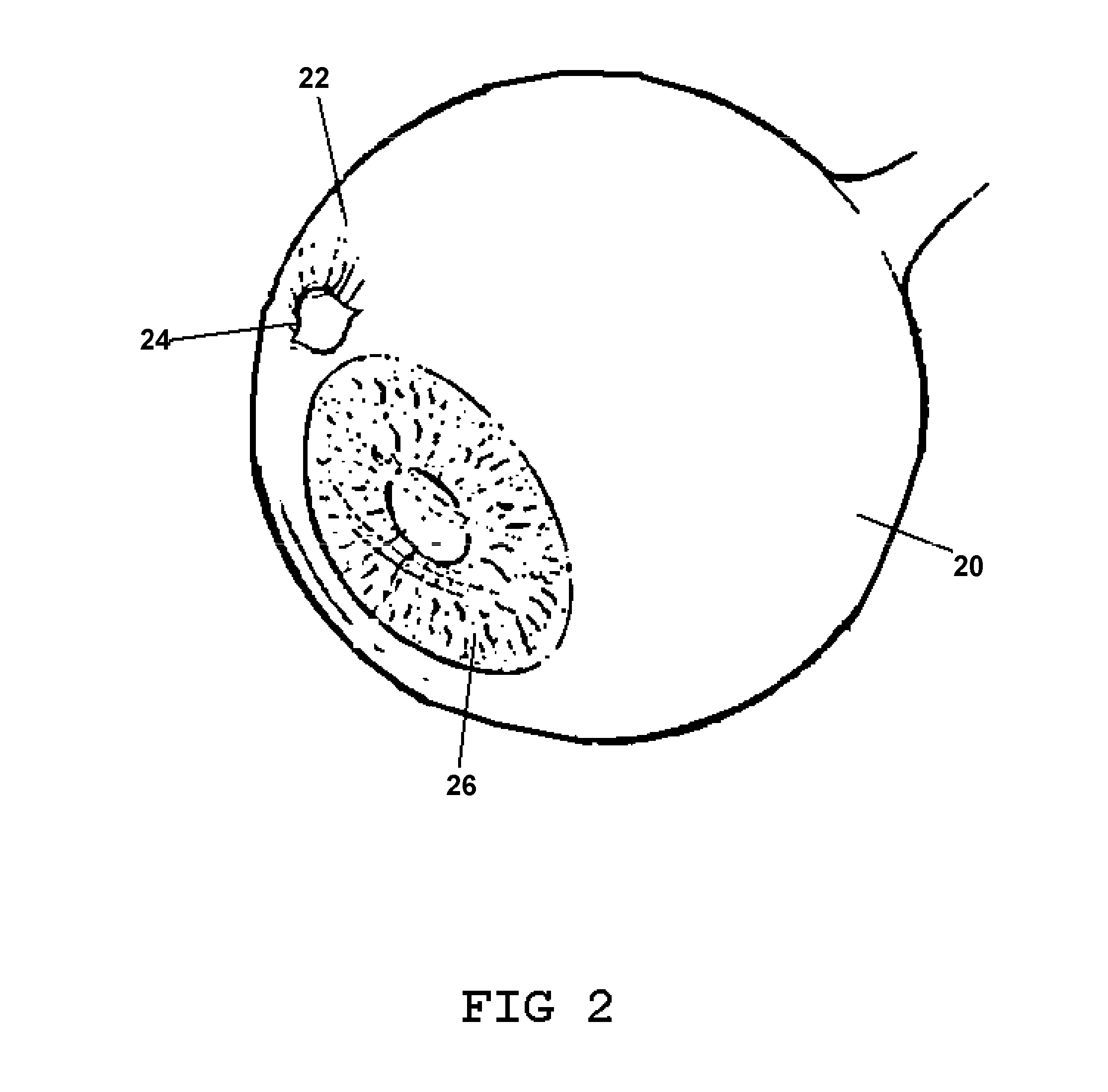
[0032]Now referring to drawings in FIGS. 1-4, wherein similar components are identified by like reference numerals, there is seen in FIG. 1 a preferred embodiment of the device 10. As shown, a nanopump 12 is positioned in an operative mounted position in the eye tissue and in an electrical connection 13 to the photovoltaic cell 14 which is operatively mounted within the clear tissue of the sclera to provide maximum light transmission thereto from outside the eye. The orientation, location, and relative size of the components of the device 10 are not limited to the depictions set forth in the figure but merely give simplified versions of the components for demonstration purposes and should not be considered limited as those skilled in the art will realize that nano-sized pumps and photovoltaic cells are made by many manufacturers all of which are considered within the scope of this intention.

[0033]A fluid intake conduit 16 having an intake aperture 15 on its distal end communicates f...


PUM


Abstract

An eye mounted device configured to actively evacuate fluid from the anterior chamber of the eye to an exterior region or the sclera of the eye. The device employs a miniature pump powered by a photovoltaic cell which is mounted in the clear corneal tissue and which may be curved in the same shape as the eye. One or a combination of pressure sensors and timers determine the duration the device evacuates fluid from the user's eye.

Description

[0001]This application claims priority to U.S. Provisional Application No. 61 / 320,960 filed on Apr. 5, 2010, and is incorporated herein in its entirety.BACKGROUND OF THE INVENTION[0002]1. Field of the Invention[0003]The disclosed device relates to sclera and cornea implants. More particularly, it relates to a device implanted into the sclera or corneal tissue of the eye to provide a means to relieve excess intraocular pressure which frequently accompanies Glaucoma.[0004]2. Prior Art[0005]In the human eye, aqueous humor is a fluid secreted into the posterior chamber of the eye, by the ciliary body. From the secretion point, it flows through the narrow cleft between the front of the lens and the back of the iris, and then escapes through the pupil into the anterior chamber of the eye. From the anterior chamber, the fluid exits the eye via the trabecular meshwork. From the trabecular meshwork, the fluid exits into Schlemm's canal.[0006]Aqueous humor is continually produced by the cilia...

Claims


Application Information

Patent Timeline
Patent Type & Authority Applications(United States)
IPC IPC(8): A61M1/00
CPCA61F9/00781
Inventor SUNALP, MURAD A.
Owner SUNALP MURAD A
Learn More