
Surgical punch

a surgical and punching technology, applied in the field of surgical punching, can solve the problems of difficult emptying of the collection chamber and hardly suitable punching, and achieve the effect of reducing the number of surgical wounds and facilitating the cutting of hard and tough bone and cartilage tissu

Active Publication Date: 2011-10-06
S U A MARTIN
View PDF10 Cites 19 Cited by
  • Summary
  • Abstract
  • Description
  • Claims
  • Application Information

AI Technical Summary

Benefits of technology

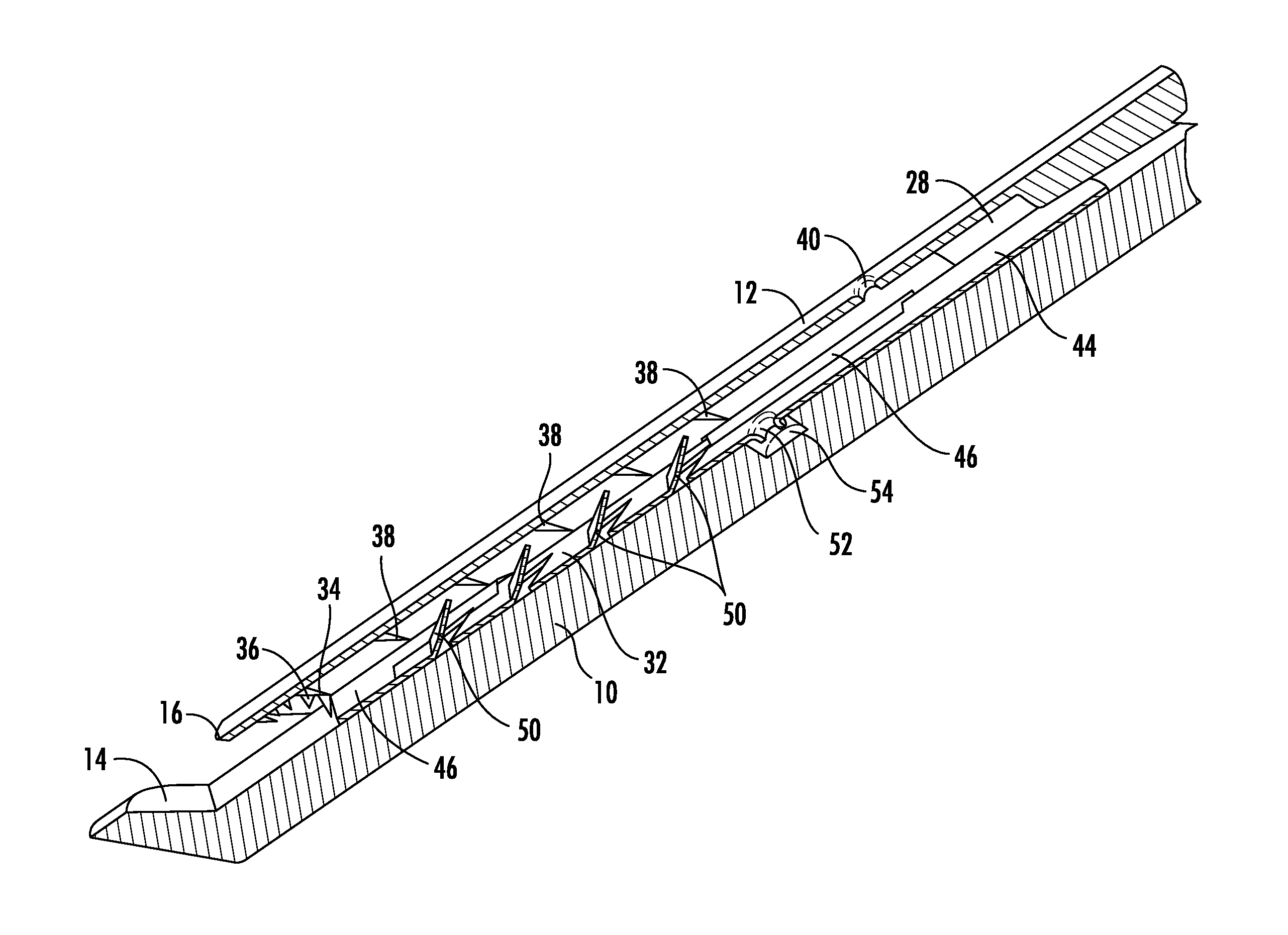
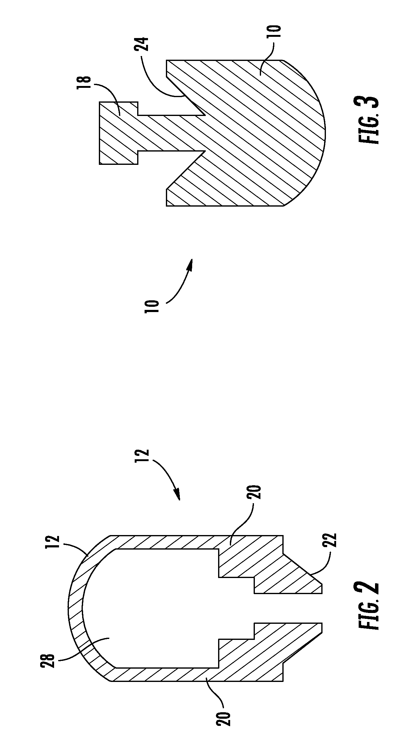
[0008]In case of the surgical punch according to the invention, the collection chamber is configured as cartridge which can be replaceably inserted in the distal end of the punch. The cartridge has a sleeve-like casing in which the punched out resected chips are collected. The cartridge is integrated in a tooth rail which is guided displaceable relative to the casing. When inserting the cartridge into the punch, the casing is fixed on the upper part of the punch in an axially non-displaceable manner, while the tooth rail is non-displaceably fixed on the lower part of the punch. In the casing, a transport serration is formed which consists of a row of teeth running in the longitudinal direction. The tooth rail has a retaining serration which also consists of a row of teeth running in the longitudinal direction. The teeth each have a tip pointing in a proximal direction so that the resected chips can be pushed in the proximal direction over the transport serration of the casing as well as over the retaining serration of the tooth rail, but are prevented by the teeth from moving in the distal direction. The transport serration of the casing of the cartridge and the retaining serration of the tooth rail form an active transport mechanism which, when actuating the punch, successively transports each of the cut off resected chips into the cartridge. Once the cartridge is filled or the surgical procedure is finished, the cartridge can be removed in a simple manner from the punch and can be replaced by a new empty cartridge. The cartridge can be produced in a cost-efficient manner from plastic or as punched and bent part from a thin sheet metal so that the cartridge can be produced as inexpensive disposable commodity. Emptying, cleaning and sterilizing the collection chamber is therefore no longer required.
[0009]In order to reliably place each of the cut off resected chips into the cartridge, the cartridge is inserted into the upper part of the punch in such a manner that the open distal end of the cartridge lies directly behind the punch blade of the upper part and abuts against the inner contour of the punch blade. Thereby it is achieved that the punch foot of the lower part comes close to the distal end of the cartridge when closing the punch and pushes the cut off resected chip into said cartridge so that the chip can be collected by the transport mechanism of the cartridge. It is advantageous here if the distal edge of the open end of the casing of the cartridge is provided with an inwardly directed tooth rim by which that resected chip is collected which is pushed by the punch foot into the cartridge.
[0010]In a particularly advantageous embodiment, the punch blade of the upper part encompasses the punch foot of the lower part so that at the end of the closing movement of the punch, the punch foot plunges into the punch blade. This has the advantage, on the one hand, that the tissue between punch foot and punch blade is cut off by a shearing cut which makes cutting hard and tough bone and cartilage tissue easier. On the other hand, with the punch completely closed, the punch foot can now plunge into the punch blade and can move directly up the distal end of the inserted cartridge so that the cut off resected chip is reliably and completely pushed into the cartridge even if a soft tissue is involved.

Problems solved by technology

The collection chamber is formed by a hollow space in the punch so that emptying the collection chamber is difficult.
Since the punch blade must have a high precision and stability, this punch is hardly suitable to produce the storage chamber as inexpensive disposable article.

Method used


Image

  • Surgical punch
  • Surgical punch
  • Surgical punch

Examples


Embodiment Construction

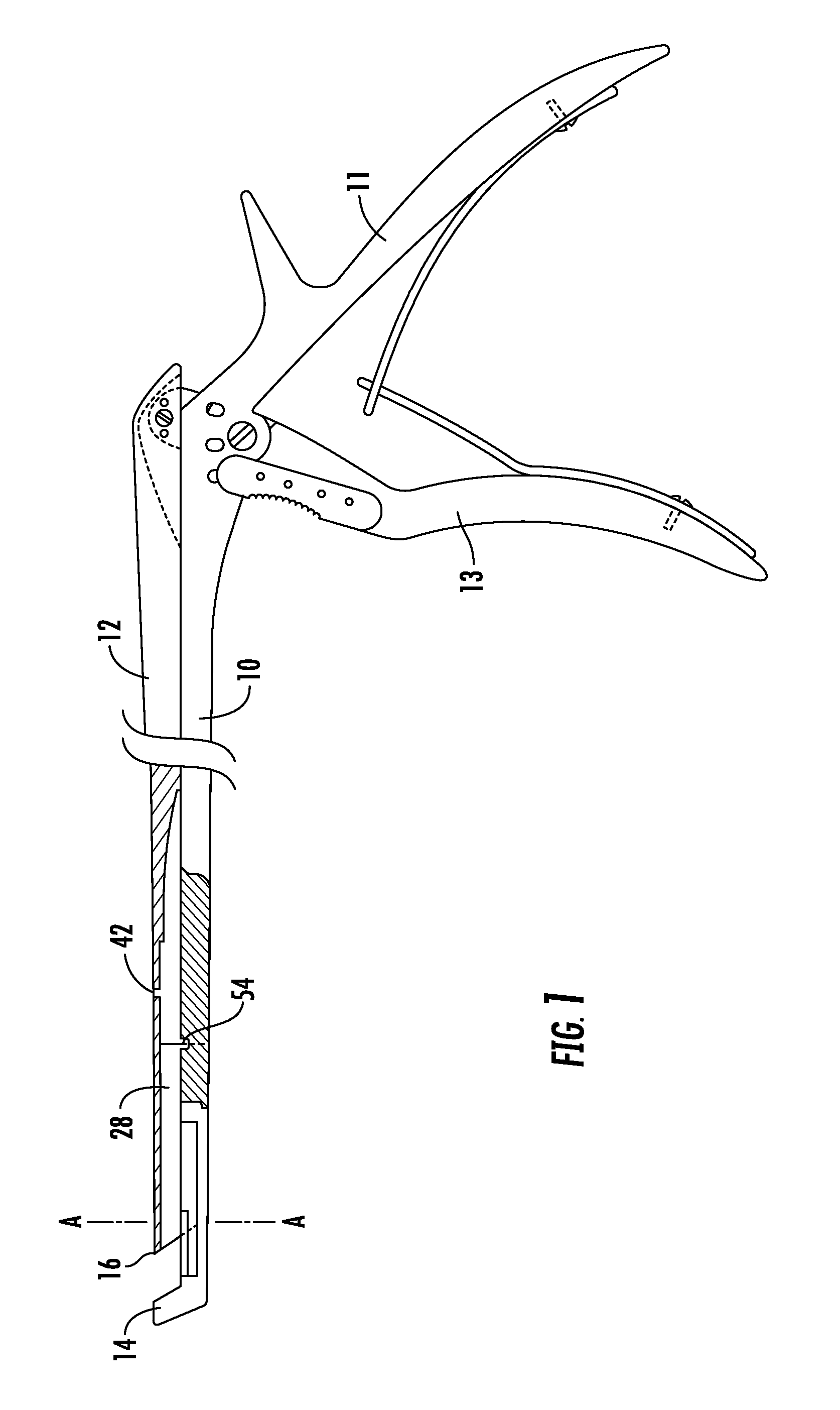
[0023]A surgical punch for resecting bone, cartilage or other tissue has a lower part 10 (shaft) on which an upper part 12 (pusher) is guided in a longitudinally displaceable manner. At the proximal end of the punch, the lower part 10 is connected to a fixed handle part 11. A handle part 13 which is pivotable towards the fixed handle part 11 is engaged with the proximal end of the upper part 12. At the distal end of the lower part 10, an angled punch foot 14 is integrally formed thereon. The distal end of the upper part 12 is formed as punch blade 16, the horseshoe-shaped contour of which corresponds to the outer circumferential contour of the punch foot 14. When pivoting the pivotable handle part 13 towards the fixed handle part 11, the upper part 12 is displaced on the lower part 10 in the distal direction. During this closing movement, the punch blade 16 is slid over the punch foot 14, and the bone, cartilage or other tissue which is present between the punch foot 14 and the punc...


PUM


Abstract

A surgical punch has a cartridge for collecting the resected chips cut off in successive punch cuts. The cartridge is a replaceable disposable commodity. The cartridge consists of a casing and a tooth rail which is guided longitudinally displaceable relative to the casing. Once the cartridge is inserted, the casing is fixed on the upper part of the punch, while the tooth rail is fixed on the lower part of the punch. A transport serration is formed in the casing. The tooth rail has a retaining serration. During the opening and closing movement of the punch, the transport serration and the retaining serration interact as transport mechanism which displaces the cut off resected chips in the cartridge in the proximal direction.

Description

CROSS REFERENCE TO RELATED APPLICATIONS[0001]This application claims the benefit of German Patent Application No. DE 10 2010 013 459.7 filed Mar. 30, 2010, which is hereby incorporated by reference in it's entirety.DESCRIPTION[0002]The invention relates to a surgical punch.[0003]Surgical punches of this type serve for removing bone, cartilage and other tissue parts. These parts are punched out in the form of small resected tissue chips, the size of which is determined by the size of the punch foot and the punch blade. To resect larger regions, usually, a plurality of punch cuts has to be carried out. In order that it is not required to remove the punch from the surgical wound after each punch cut to remove the resected chip, it is known to collect a relatively high number of cut off resected chips in a collection chamber of the punch.[0004]From U.S. Pat. No. 5,582,618 A, a surgical punch is known with which the successively cut off resected chips are pushed by means of a punch foot ...

Claims


Application Information

Patent Timeline
IPC IPC(8): A61B17/16
CPCA61B17/1611
Inventor MIKLOSOVIC, MIROSLAV
Owner S U A MARTIN
Learn More