System and method for monitoring dissolved gases in insulating oil of power transformers, reactors, on-load tap changers, current transformers, potential transformers, condensive bushings as well as similar high voltage equipments immersed in oil

a technology of insulating oil and monitoring system, applied in the field of system and method, to achieve the effect of low cost and high cos

Active Publication Date: 2011-10-06
SANTOS EDUARDO PEDROSA
View PDF4 Cites 40 Cited by
  • Summary
  • Abstract
  • Description
  • Claims
  • Application Information

AI Technical Summary

Benefits of technology

[0022]Due to the high costs associated to the state of the art monitoring systems, the economic infeasibility of their use in small size transformer and other equipment used at the thousands in electric power distribution systems, leaving those equipment deprived of on-line monitoring and subject to catastrophic failures.
[0023]The invention aims to continuously and in real time monitoring the concentration of gases in the insulating oil in high voltage equipment, such as, for instance, power transformers, reactors, condensive bushings, current and potential transformers among others, made by means of an orifice of reduced diameter, with no need of any tubing along the transformer, which will assure the access to a sample of oil which will the best representative of what may be going on inside the high voltage equipment.
[0032]The possibility of very low cost versions building, only acting as a “gas switch” for alarm, allowing monitoring of small size transformers and other equipment used at the thousands in power distribution.

Problems solved by technology

Therefore, any inside fault occasionally occurred in an equipment, such as overheating points, bad contacts, partial discharges, arcs and others may provoke either oil or paper molecule breakage, generating gases that will dissolve into the oil.
However, this is obtained by increasing oil leakage risks along the closed circuit where such oil circulates, due to the great number of elements as well as of sealed connections needed, which encloses two valves on the transformer tank wall, the tubing connections to these two valves as well as the connections of both same tubing to the measurement equipment, besides the connections inside the measurement equipment.
Besides the greater number of connections and sealing elements needed, such arrangement contributes to a larger risk of leakages also due to the several meters length of mentioned tubing, that are, therefore, exposed to a greater risk of accidental damages during the transformer's maintenance works, where going up and down of maintenance personnel on its lateral walls as well as same personnel walking on its upper cover accomplishing various tasks in such places, usually using heavy tools, is very common.
The existence of such two cylinders brings the need of their periodic replacement, for their contents are gradually consumed during the measurement system operation.
When taking into consideration that one only electric power concessionary may have either hundreds or even thousands of transformers in its installed base, besides other high voltage equipment immersed in oil, the simple periodic replacement of cylinders may undertake a great extent, with the need of creating specific professional teams to take care of the gases in real time monitoring equipment, which consequently provokes an increase in maintenance costs as well as a deviation of the maintenance engineering focusing which should always be fully directed to the transformer.
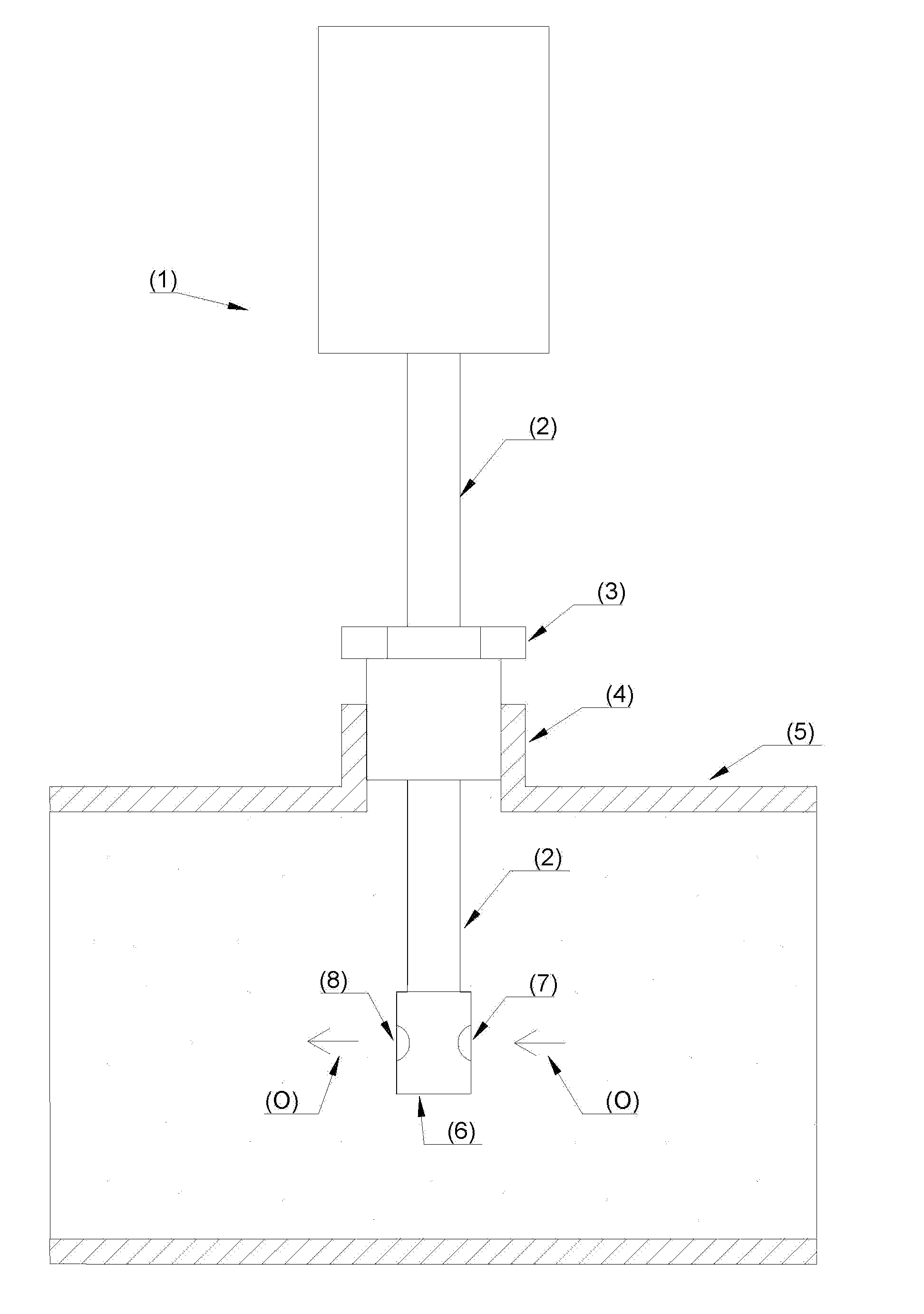
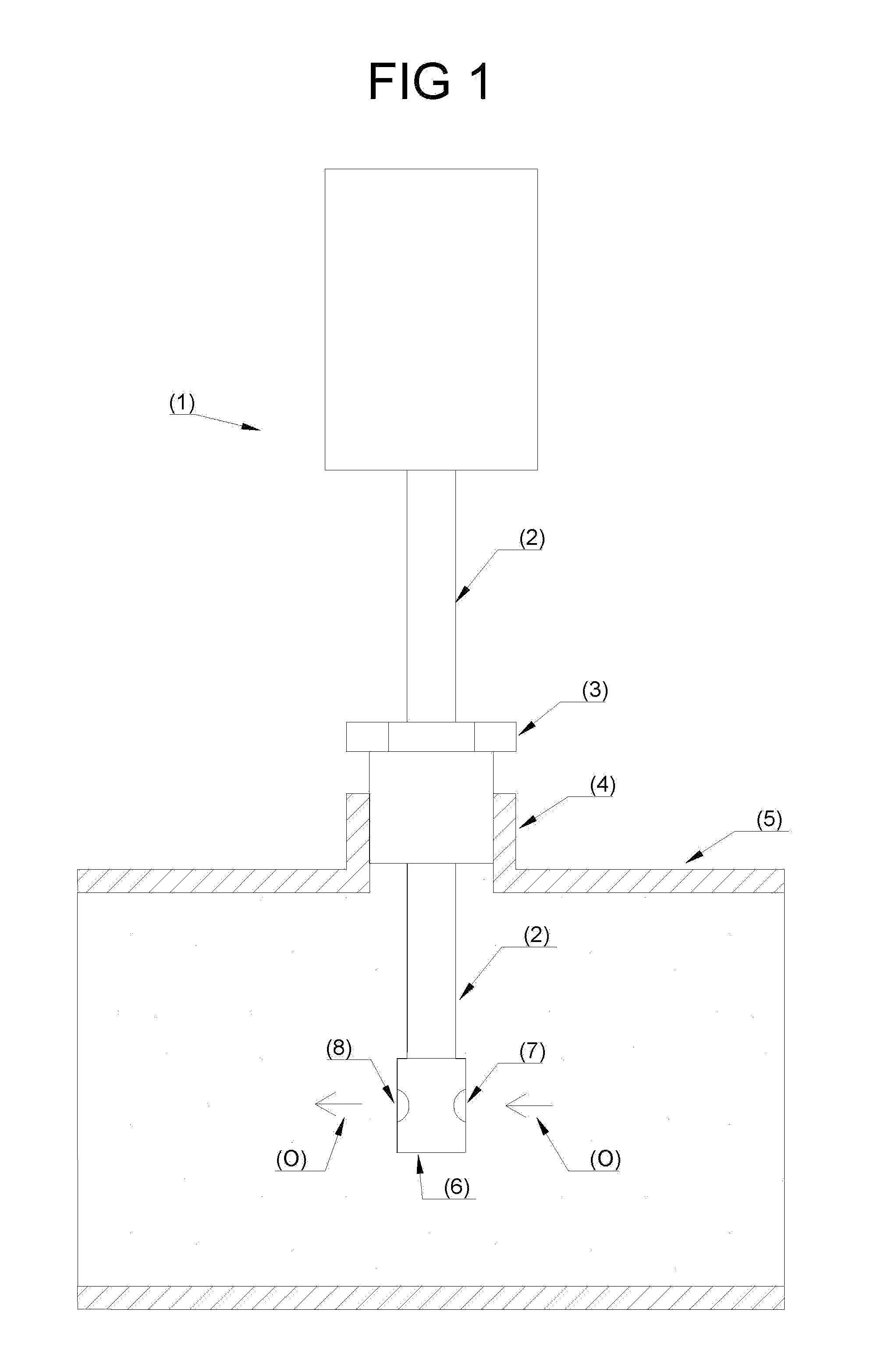
However, the draining valve location at the lowest tank point, at a level below the active part, where the heat that provokes the oil circulation inside the transformer is generated, may lead the oil to therein stagnate, and the circulation caused by the heating of the measurement equipment to merely be local, and, therefore, poorly representing the dissolved gases in the remainder portion of the transformer.
Situations may arise, however, where such pressure difference significantly increases, which may damage the membrane and cause an oil leakage through it, which puts the state of the art monitoring equipment out of order and causes oil pouring in the environment.
Examples of situations that may cause such damages to the membrane are the vacuum creation inside the transformer tank during tests or oil treatment processes, and an excessive pressure or vacuum occurring, respectively, during the installation or the removal of the valve of the transformer of the monitoring equipment without opening the air purging orifice to allow a pressure balancing between the valve inside and the environment.
In the case of systems with piping circulation systems, the high leakage risks along the oil closed circulation system, due to great number of elements and connections needed as well as to the great tubing length, that are exposed to accidental damages;In the case of systems with connection to one only valve, the requirement of using a relatively large diameter valve which will increase installation costs of new transformers;Due yet to the requirement of using large diameter valve, the obligation of a connection to the draining valve of the transformer in many installations performed in transformer already in operation, obliging to the removal of the monitoring system each time the valve must be used in another application;In a case of installation at the draining valve, the risk for the dissolved gases measurement to be done in stagnated oil, poorly representative of the phenomena that occur in the transformer, which will lead to a low quality diagnosis;The use, in some monitoring systems, of gas cylinders that must be periodically replaced, incorporating a new item that will require a periodic preventive maintenance, when the purpose of monitoring is the periodic maintenance to be eliminated.
As an electric power utility may possess hundreds or thousands of transformers, there will be hundreds or thousands of cylinders to maintain, which also contributes to deviate the focus of the maintenance professionals from their main tasks;The risk of damages to the monitoring equipment semi-permeable membrane in case of overpressure or vacuum that may occur either when installing and removing the system or when the transformer would be submitted to maintenance and tests;The risks of environment contaminating in case of insulating oil leakage, due to the aforementioned factors;Due to the high costs associated to the state of the art monitoring systems, the economic infeasibility of their use in small size transformer and other equipment used at the thousands in electric power distribution systems, leaving those equipment deprived of on-line monitoring and subject to catastrophic failures.

Method used


Image

  • System and method for monitoring dissolved gases in insulating oil of power transformers, reactors, on-load tap changers, current transformers, potential transformers, condensive bushings as well as similar high voltage equipments immersed in oil
  • System and method for monitoring dissolved gases in insulating oil of power transformers, reactors, on-load tap changers, current transformers, potential transformers, condensive bushings as well as similar high voltage equipments immersed in oil
  • System and method for monitoring dissolved gases in insulating oil of power transformers, reactors, on-load tap changers, current transformers, potential transformers, condensive bushings as well as similar high voltage equipments immersed in oil

Examples


Embodiment Construction

[0040]The new invention herein described deals with a “SYSTEM AND METHOD FOR MONITORING DISSOLVED GASES IN INSULATING OIL OF POWER TRANSFORMERS, REACTORS, ON-LOAD TAP CHANGERS, CURRENT TRANSFORMERS, POTENTIAL TRANSFORMERS, CONDENSIVE BUSHINGS AS WELL AS SIMILAR HIGH VOLTAGE EQUIPMENT IMMERSED IN OIL”, mainly consisting of a system that is coupled to one only orifice for the insulating oil accessing, being such orifice of small diameter and avoiding the use of tubing along the transformer, which allows its installation, for instance, at the orifices present in air purging radiators, thus assuring to the monitoring system the access to an oil sampling that will represent in an excellent manner what is going on inside the high voltage equipment. Besides allowing a simple and safe installation in the high voltage equipment, such system also has the self-calibration recourse as well as several possible user's interfaces, as well analogical as digital.

[0041]More particularly, referring to...


PUM

PropertyMeasurementUnit
voltageaaaaaaaaaa
semi-permeableaaaaaaaaaa
concentrationaaaaaaaaaa

Abstract

“SYSTEM AND METHOD FOR MONITORING DISSOLVED GASES IN INSULATING OIL OF POWER TRANSFORMERS, REACTORS, ON-LOAD TAP CHANGERS, CURRENT TRANSFORMERS, POTENTIAL TRANSFORMERS, CONDENSIVE BUSHINGS AS WELL AS SIMILAR HIGH VOLTAGE EQUIPMENTS IMMERSED IN OIL”, remarkably consisting of a system that couples to an orifice for the insulating oil accessing, assuring to the monitoring system the access to an oil sampling with a good representativity of what is going on inside the high voltage equipment, besides allowing a simple and safe installation, and also presenting to the user several resources and interfaces.

Description

FIELD OF THE INVENTION[0001]This system and method aims at continuously and in real time monitoring the concentration of dissolved gases in the insulating oil of high voltage equipment, such as power transformers, reactors, condensive bushings, current transformers, potential transformers and others, in order to quickly detect faults occurrence when they are still in an incipient stage, thus avoiding catastrophic failures, frequently followed by explosion and fire, which may cause risks to the operation and maintenance personnel and may lead to the whole loss of the involved high voltage equipment.BACKGROUND OF THE INVENTION[0002]Power transformers, reactors, condensive bushings as well as other high voltage equipment are largely used in electric power generation, transmission and distribution systems, where they perform several essential roles, such a way that the continuity of the power supplying depend, for the most part, upon the reliability of such equipment.[0003]The aforement...

Claims


Application Information

Patent Timeline
Patent Type & Authority Applications(United States)
IPC IPC(8): G06F19/00G01N33/28
CPCG01N33/2841
Inventor SANTOS, EDUARDO PEDROSA
Owner SANTOS EDUARDO PEDROSA
Why Eureka
Try Eureka