Disk array configuration program, computer, and computer system

a disk array and configuration program technology, applied in the field of disk array configuration programs, can solve the problems of reducing cost-effectiveness and shortening the life of the ssd, and achieve the effects of reducing the number of write operations to the flash memory, enhancing the endurance of the program-erase cycle, and improving the performance of the file relocation

Inactive Publication Date: 2011-10-06
HITACHI LTD
View PDF4 Cites 21 Cited by
  • Summary
  • Abstract
  • Description
  • Claims
  • Application Information

AI Technical Summary

Benefits of technology

The disk array configuration program in accordance with the present invention, when relocating a file to the flash memory, caches a small-size file without immediately writing it to the flash memory. Thus, t...

Problems solved by technology

Since the conventional methods do not take such drawbacks into consideration, it is possible ...

Method used


Image

  • Disk array configuration program, computer, and computer system
  • Disk array configuration program, computer, and computer system
  • Disk array configuration program, computer, and computer system

Examples


embodiment 1

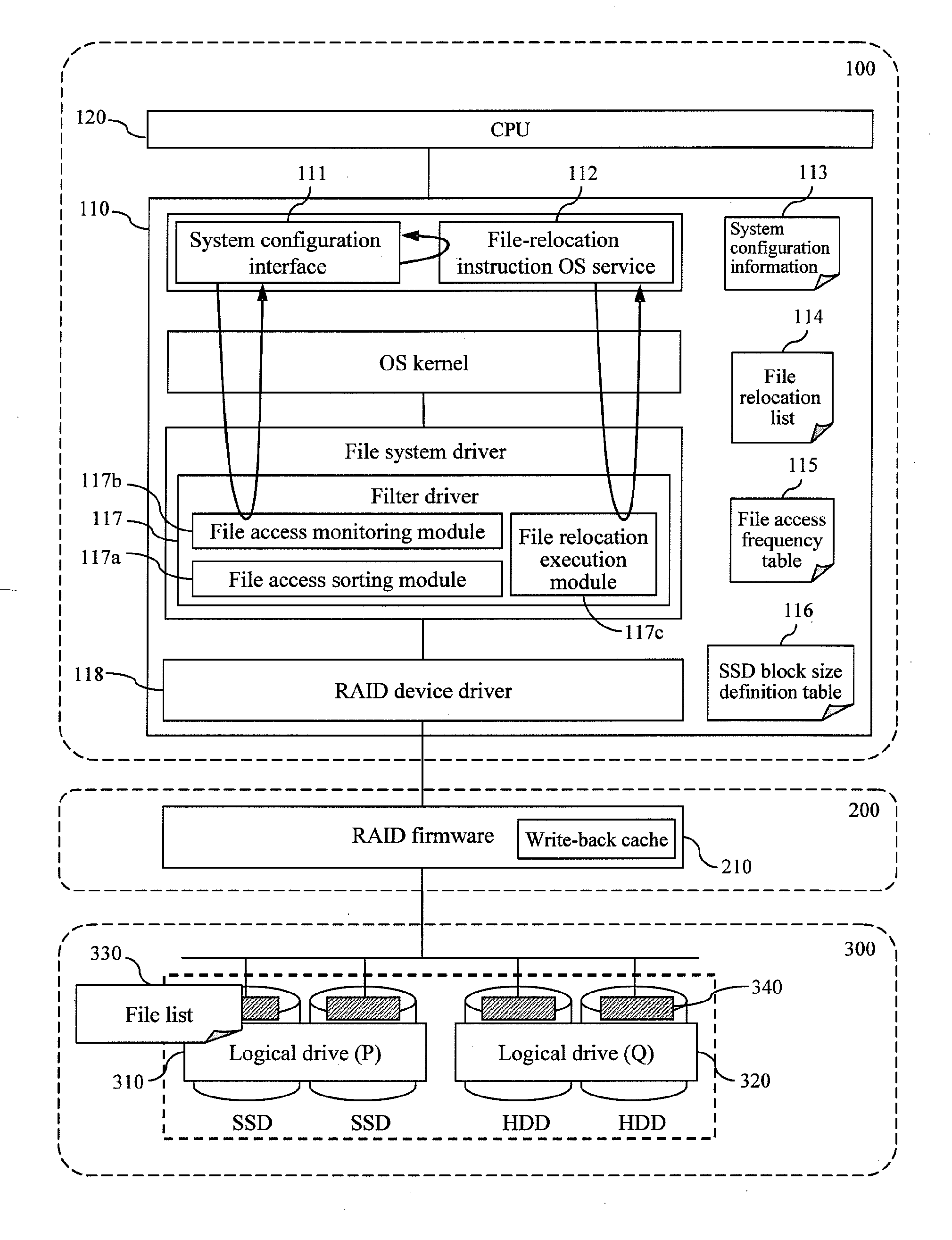
FIG. 1 is a functional block diagram of a computer 100 that executes a disk array configuration program in accordance with Embodiment 1 of the present invention. The computer 100 includes a main memory unit 110 and a CPU 120. The computer 100 is connected to a RAID controller card 200. The RAID controller card 200 is connected to a storage device 300.

In the storage device 300, a disk array is configured with the function of a RAID device driver 118. The computer 100 delegates some processes with a high operation load such as a parity operation to the RAID controller card 200.

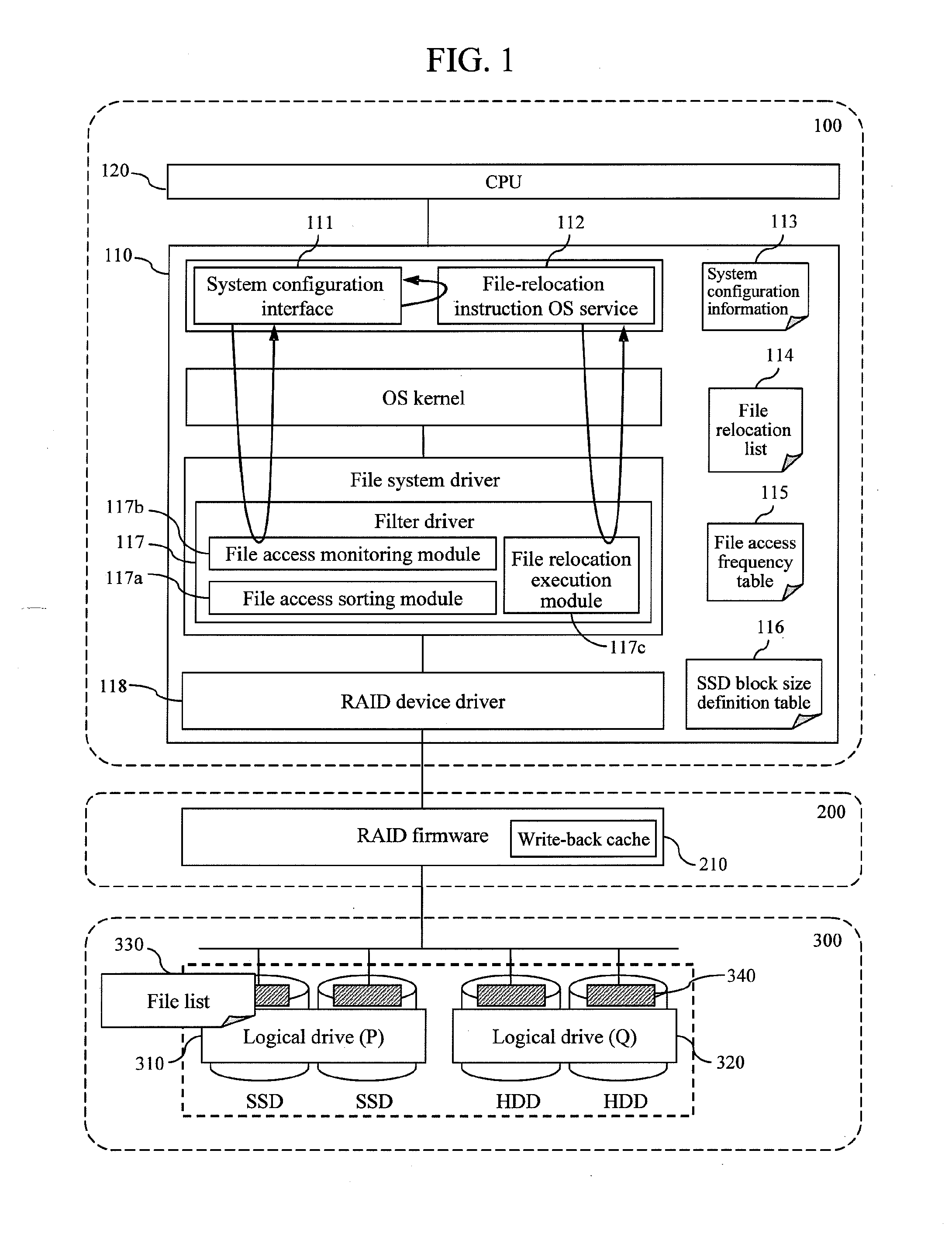
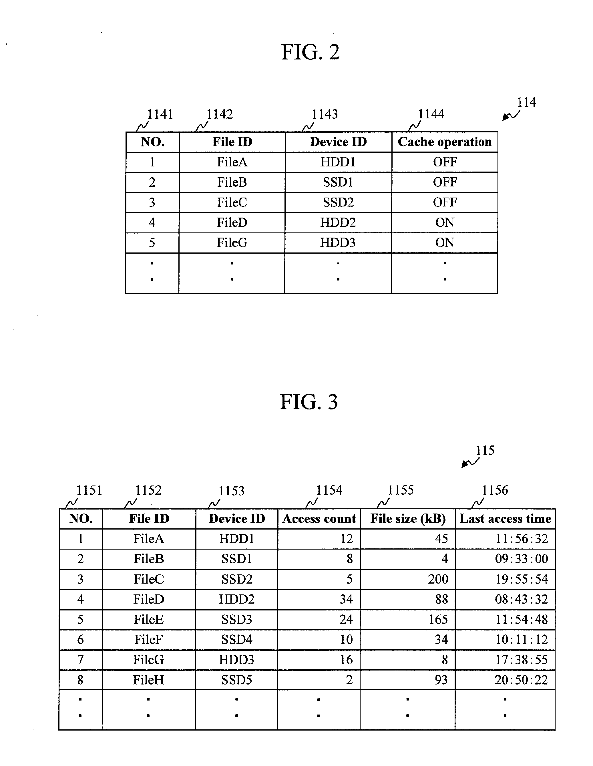
The main memory unit 110 stores therein a system configuration interface 111, a file-relocation instruction OS (Operating System) service 112, system configuration information 113, a file relocation list 114, a file access frequency table 115, an SSD block size definition table 116, a filter driver 117, and a RAID device driver 118. In addition, software such as an OS kernel or a file system driver is read into ...

embodiment 2

Embodiment 2 of the present invention will describe a specific example of the system configuration interface 111. The configuration of each device is the same as that in Embodiment 1.

Embodiment 1 described that the system configuration interface 111 determines whether or not the logical drive (P) 310 and the logical drive (Q) 320 should hold identical files in an overlapped manner. Hereinafter, the influence of the overlapped holding of identical files on the entire data input / output performance of the storage device 300 will be examined.

In Embodiment 1, when the logical drive (P) 310 and the logical drive (Q) 320 are configured to hold files in an overlapped manner, the file access sorting module 117a should perform writing to both the logical drives. In such a case, the apparent write speed of the entire storage device 300 will be lower than that when writing is performed only to the logical drive (Q) 320. Meanwhile, if each of the logical drive (P) 310 and the logical drive (Q) 3...

embodiment 3

Although each of Embodiments 1 and 2 has described an example in which the system configuration interface 111, the file-relocation instruction OS service 112, the filter driver 117, and the RAID device driver 118 are implemented as the “disk array configuration program,” similar functions can be implemented using hardware such as a circuit device.


PUM


Abstract

To improve the data input/output performance of a disk array with a hybrid configuration of flash memory and HDDs. A computer that executes a disk array configuration program in accordance with the present invention, when relocating a file from a hard disk to flash memory, stores the file in cache memory without immediately writing the file to the flash memory if the file size is smaller than the block size of the flash memory.

Description

CLAIM OF PRIORITYThe present application claims priority from Japanese patent application JP 2010-076529 filed on Mar. 30, 2010, the content of which is hereby incorporated by reference into this application.BACKGROUND OF THE INVENTION1. Field of the InventionThe present invention relates to a technique for configuring a disk array.2. Background ArtA flash memory device such as an SSD (Solid State Disk) that uses NAND flash memory as a storage medium (hereinafter, such flash memory device shall be referred to as an SSD) is a very fast drive with an input / output performance of about 30 times that of an HDD (Hard Disk Drive). With the advent of SSDs, it has become possible to implement a disk array with a faster speed than those of the conventional disk arrays (RAID: Redundant Arrays of Inexpensive (or Independent) Disks). However, the cost of an SSD per unit of storage capacity is as high as about five times that of an HDD, while the storage capacity of an SSD is as low as about ⅕ to...

Claims


Application Information

Patent Timeline
IPC IPC(8): G06F12/02
CPCG06F3/0616G06F3/0647G06F2212/261G06F12/0866G06F2212/217G06F3/0685
Inventor GOMYO, MASAYUKIMARUOKA, SHINJI
Owner HITACHI LTD
Why Eureka
Try Eureka