
Ion sensing circuit

a technology of ion sensing circuit and ion sensing circuit, applied in the field of circuits, can solve the problems of increased circuit assembly complexity, added design cost, and increased design complexity of conventional ion sensing circuits, and achieve the effect of simplifying design

Inactive Publication Date: 2011-10-13
NATIONAL CHI NAN UNIVERSITY
View PDF2 Cites 6 Cited by
  • Summary
  • Abstract
  • Description
  • Claims
  • Application Information

AI Technical Summary

Benefits of technology

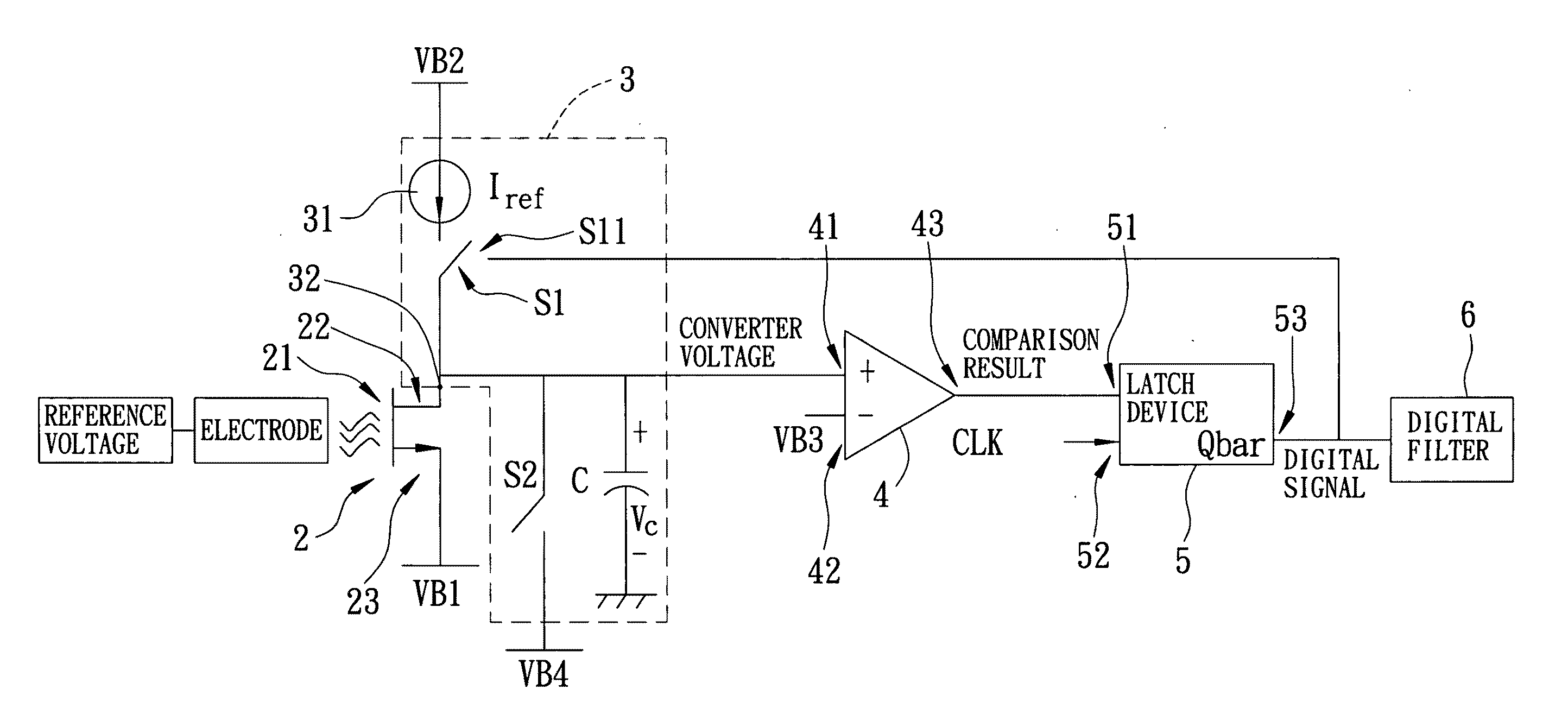
The present invention provides an ion sensing circuit with a simplified design that overcomes the disadvantages of prior art. The circuit includes an ion sensing element, a current-to-voltage converter, a comparator, and a latch. The comparator compares the converted voltage with a threshold voltage to form a comparison result. The latch samples the output of the comparator and generates a digital signal, which is used by the current-to-voltage converter for converting the sensing current to the converted voltage. The technical effect of this invention is to provide a more efficient and accurate ion sensing circuit with improved precision and reliability.

Problems solved by technology

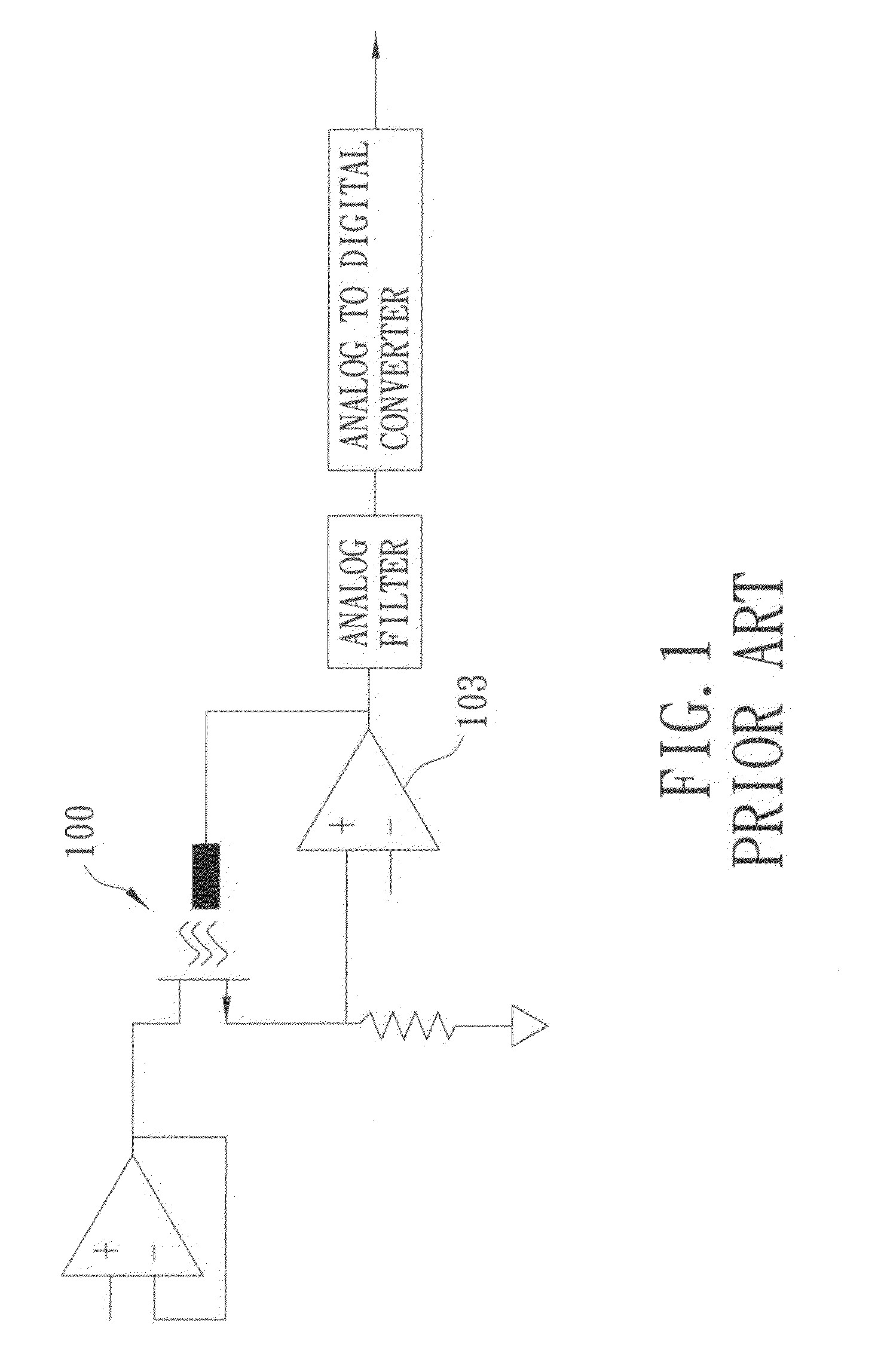
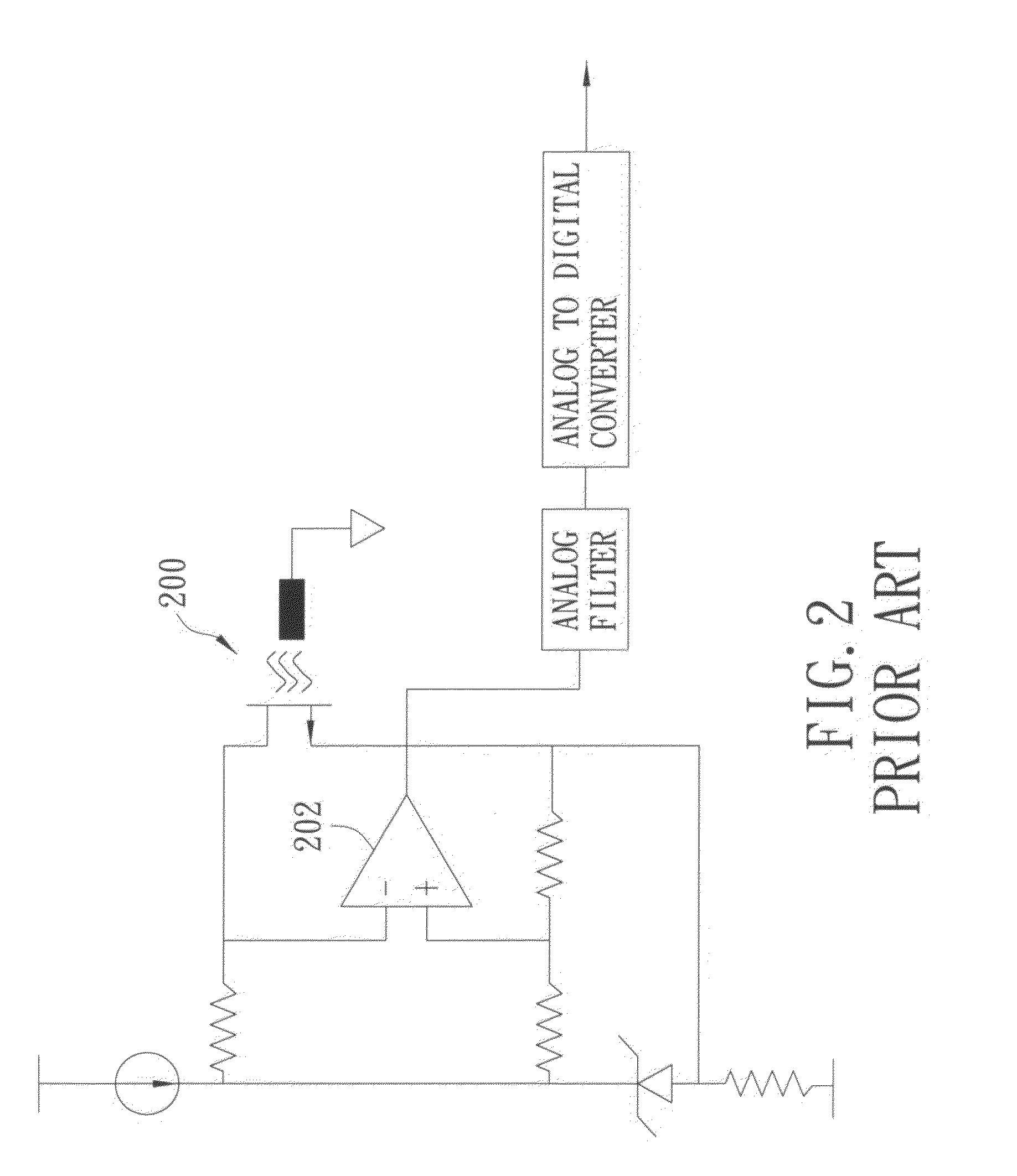
Accordingly, both conventional ion sensing circuits may incur added design costs and increased circuit assembly complexity.
In addition, for purposes of reducing noise, the conventional ion sensing circuits may include additional increased design complexity with respect to the operational amplifiers.

Method used


Image

  • Ion sensing circuit
  • Ion sensing circuit
  • Ion sensing circuit

Examples


Embodiment Construction

Before the present invention is described in greater detail with reference to the accompanying preferred embodiments, it should be noted herein that like elements are denoted by the same reference numerals throughout the disclosure.

Referring to FIG. 3, the first preferred embodiment of an ion sensing circuit according to the present invention is configured for detecting an ion concentration of an electrolytic solution for generating a related digital signal. The first preferred embodiment includes an ion sensing component 2, a current-to-voltage converter 3, a comparator 4, a latch device 5, and a digital filter 6.

The ion sensing component 2 is configured for exposure to an electrolytic solution, which causes it to generate a sensing current based on the ion concentration of the electrolytic solution, and includes a first end 21 for receiving a reference voltage, a second end 22 for outputting the sensing current related to the ion concentration of the electrolytic solution, and a t...


PUM

PropertyMeasurementUnit
ion concentrationaaaaaaaaaa
voltageaaaaaaaaaa
threshold voltageaaaaaaaaaa

Abstract

An ion sensing circuit includes an ion sensing element configured for exposure to an electrolytic solution and control of a sensing current through the ion sensing element according to an ion concentration of the electrolytic solution. The ion sensing circuit further includes a current-to-voltage converter coupled electrically to the ion sensing element for generating a converted voltage from the sensing current. The ion sensing circuit also includes a comparator coupled electrically to the current-to-voltage converter for comparing the converted voltage and a threshold voltage to form a comparison result. In addition, the ion sensing circuit includes a latch coupled electrically to the comparator and the current-to-voltage converter. The latch is configured for sampling the output of the comparator according to a clock signal to generate a digital signal used by the current-to-voltage converter for converting the sensing current to the converted voltage.

Description

CROSS-REFERENCE TO RELATED APPLICATIONThis application claims priority of Taiwanese Application No. 099111407, filed on Apr. 13, 2010.BACKGROUND OF THE INVENTION1. Field of the InventionThe invention relates to a circuit, and more particularly to an ion sensing circuit.2. Description of the Related ArtAn ion-sensitive field-effect transistor (abbreviated as ISFET) is made by removing metal from the gate of an ordinary Metal-Oxide-Semiconductor Field-Effect Transistor (abbreviated as MOSFET) to be exposed to a solution. When a reference voltage used as a direct current bias voltage is placed into the solution to cause an electrolytic change of the solution, the channel current of the ISFET varies according to the ion (such as H+) concentration in the solution. Because the ISFET includes electrodes and the field-effect transistor, the ISFET can be incorporated with other electronic components to fabricate an ion sensing circuit that may be applied to biological medicine, analysis of w...

Claims


Application Information

Patent Timeline
Patent Type & Authority Applications(United States)
IPC IPC(8): G01N27/28
CPCG01N27/4148
Inventor SUN, TAI-PINGCHEN, CHUNG-YUANSHIEH, HSIU-LICHING, TAK-SHING
Owner NATIONAL CHI NAN UNIVERSITY
Learn More