Compact Inhomogeneous Permanent Magnetic Field Generator for Magnetic Resonance Imaging

a permanent magnetic field and generator technology, applied in the direction of magnetic measurement, instruments, measurement devices, etc., can solve the problems of physiological limits to the rate of change of magnetic field, large switched gradient field is practically difficult, etc., to achieve large static gradient, reduce leakage, and enhance the effect of the pole system

Inactive Publication Date: 2011-10-13
TEKLEMARIAM GRUM +2
View PDF20 Cites 35 Cited by
  • Summary
  • Abstract
  • Description
  • Claims
  • Application Information

AI Technical Summary

Benefits of technology

[0010]Based on the above considerations, it is an object of embodiments of the present invention to provide a magnet system with a large static gradient that is primarily suitable for neurological studies by MRI and is very compact, lightweight and easy to site.
[0012]Accordingly, such an arrangement of permanent magnet arrays has the effect of concentrating the flux generated in the center while minimizing the flux externally. A C-type yoke system and return fixture further concentrates the flux in the center and minimizes leakage while also being used to support the permanent magnets.
[0013]Another objective of embodiments of the invention is to provide the ability to generate a large static gradient. This is achieved by eliminating altogether the symmetric bottom half of the PM blocks.
[0014]A further means of controlling the magnetic field in the center is provided by poles asymmetrically arranged top and bottom to form a constant potential surface and there between generate a linear static gradient magnetic field. The pole system's effectiveness is enhanced by the drastically reduced flux generated in it due to the combination of the disk and ring portions of the PM blocks.

Problems solved by technology

However, large switched gradient fields are practically difficult and there are physiological limits to the rate of change of magnetic fields.

Method used


Image

  • Compact Inhomogeneous Permanent Magnetic Field Generator for Magnetic Resonance Imaging
  • Compact Inhomogeneous Permanent Magnetic Field Generator for Magnetic Resonance Imaging
  • Compact Inhomogeneous Permanent Magnetic Field Generator for Magnetic Resonance Imaging

Examples


Embodiment Construction

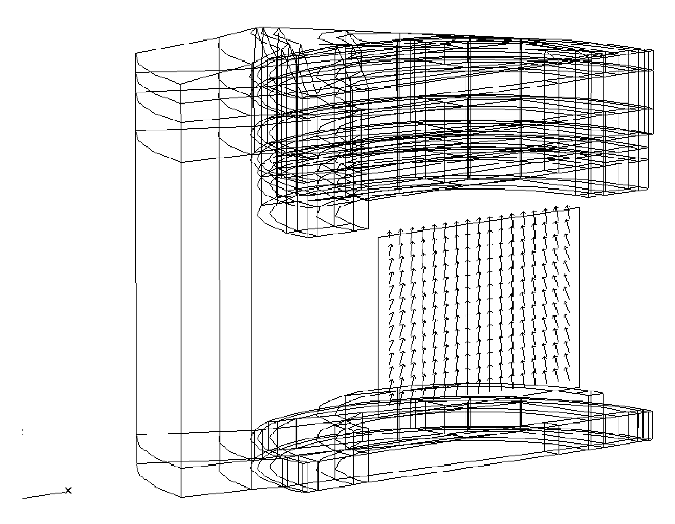
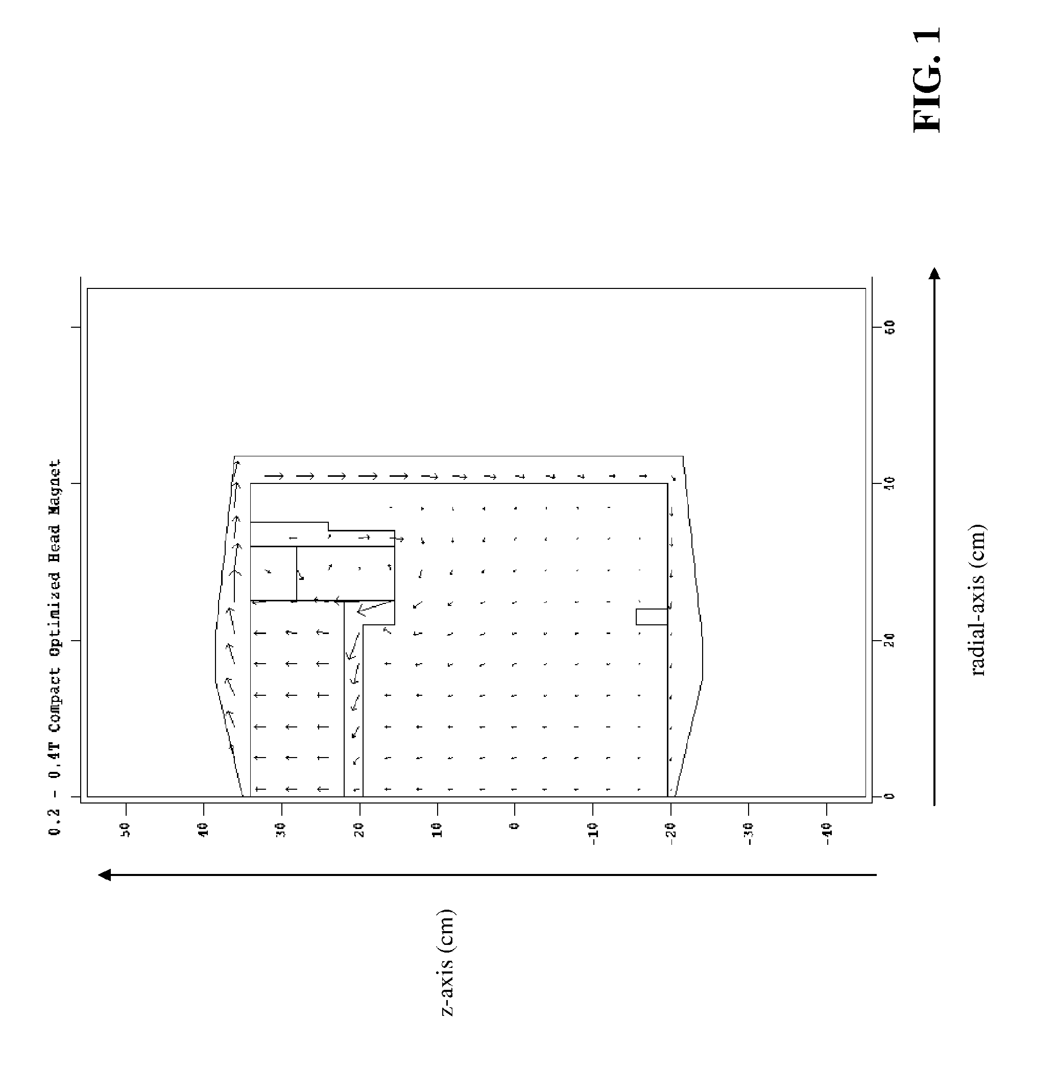
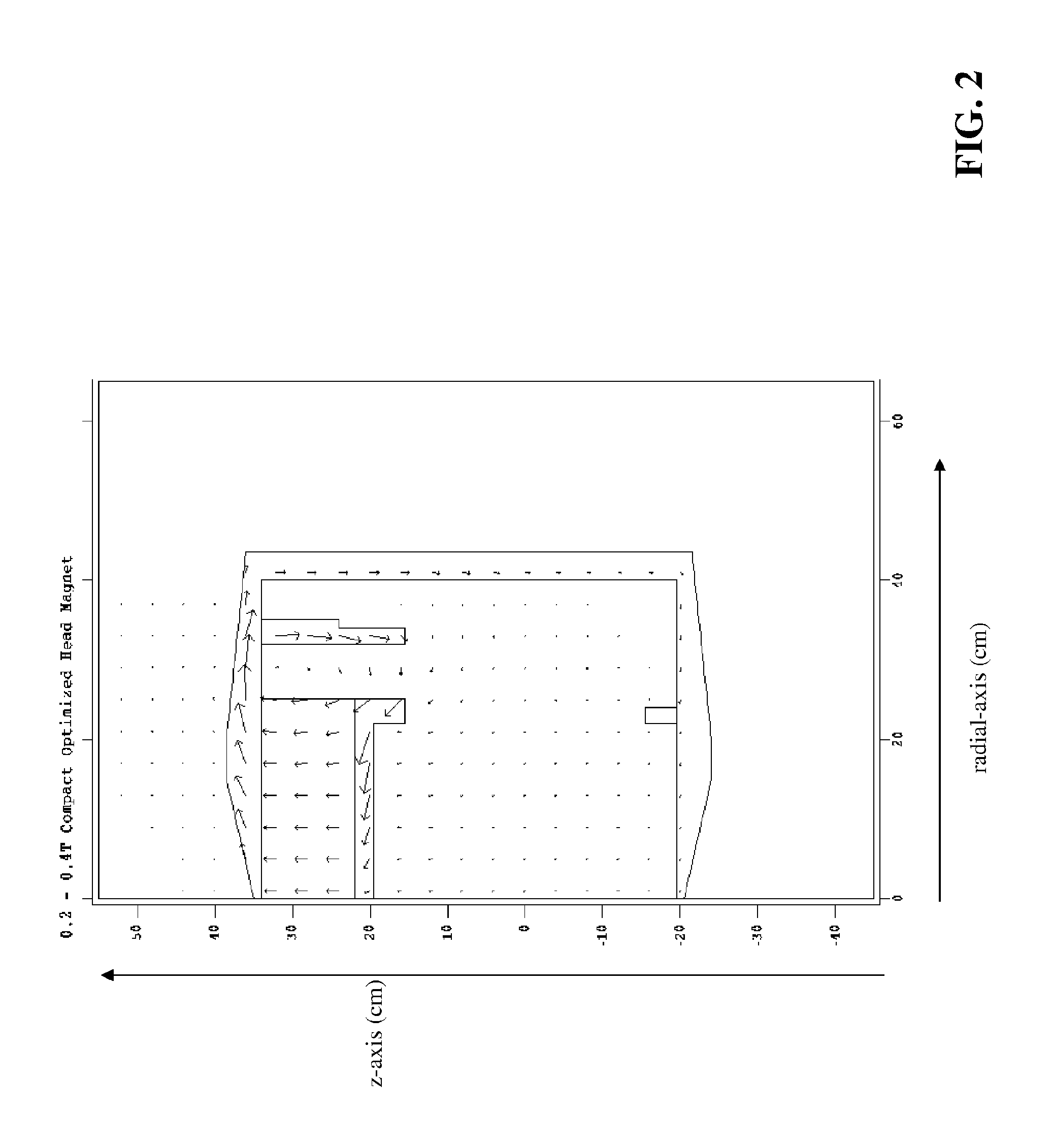
[0028]An inhomogeneous permanent magnetic field generator assembly will now be described in detail with reference to the accompanying drawings. It will be appreciated that, while the following description focuses on an assembly that generates magnetic fields for magnetic resonance imaging, the systems and methods disclosed herein have wide applicability. Notwithstanding the specific example embodiments set forth below, all such variations and modifications that would be envisioned by one of ordinary skill in the art are intended to fall within the scope of this disclosure.

[0029]The following design for an efficient compact MRI allows the magnet to shrink in size while trading off field inhomogeneity for increased field strength. With this advance, use can be made of compact magnets that have significant inhomogenieties. This permits the magnets to be lighter weight and have a smaller footprint.

[0030]Advances from fields such as quantum information processing have also led to ‘optima...


PUM


Abstract

A magnet assembly primarily for use in MRI applications is disclosed. The magnet assembly is composed of a single disk and ring permanent magnet set connected to a C-type magnet yoke and return fixture with asymmetrically arranged poles. Together, the permanent magnets create a strong magnetic field that has a large static gradient in the central enclosure. The magnet assembly is primarily designed for diffusion based MRI scanning but can perform routine MRI scanning as well.

Description

CROSS-REFERENCE TO RELATED APPLICATIONS[0001]This application claims the benefit of U.S. App. No. 61 / 138,940, filed on Dec. 18, 2008, entitled “COMPACT INHOMOGENEOUS PERMANENT MAGNETIC FIELD GENERATOR FOR MAGNETIC RESONANCE IMAGING.” the entire contents of which is incorporated herein by reference.STATEMENT REGARDING FEDERALLY SPONSORED RESEARCH OR DEVELOPMENT:[0002]Not ApplicableREFERENCE TO SEQUENCE LISTING, A TABLE, OR A COMPUTER PROGRAM LISTING COMPACT DISC APPENDIX[0003]Not ApplicableBACKGROUND OF THE INVENTION[0004]1. Field of the Invention[0005]The invention relates to permanent magnet designs that can generate very strong and inhomogeneous fields primarily for NMR, MRI and MRT use.[0006]2. Description of the Related Art[0007]In Magnetic Resonance Imaging (MRI) there is a need for compact, very efficient and robust imaging systems that can perform high quality neurological MRI studies. Specifically, it is desirable for these systems to be capable of diffusion, angiography and...

Claims


Application Information

Patent Timeline
Patent Type & Authority Applications(United States)
IPC IPC(8): G01R33/34
CPCG01R33/3806G01R33/3808G01R33/56341G01R33/3873G01R33/383
Inventor TELEMARIAM, GRUMLIAN, JIANYUCORY, DAVID
Owner TEKLEMARIAM GRUM
Why Eureka
Try Eureka