Image forming system, linking apparatus and recording medium

Active Publication Date: 2011-10-13
KONICA MINOLTA BUSINESS TECH INC
View PDF1 Cites 13 Cited by
  • Summary
  • Abstract
  • Description
  • Claims
  • Application Information

AI Technical Summary

Benefits of technology

[0011]It is an object of the present invention to provide an image forming system capable of easily realizing suppression of the returns from the power saving mode while avoiding the concentration of the loads to the server, and to provide a technology related to the image forming system.

Problems solved by technology

Therefore, in particular, when a frequency of the access from the external computer is large, the image forming apparatus frequently returns from the sleep state, and an effect of the reduction of the power consumption cannot be obtained sufficiently.
However, in a proxy response technology by the server, such problems are present that concentration of loads to the server occurs since a variety of processing is performed in the server intensively.

Method used


Image

  • Image forming system, linking apparatus and recording medium
  • Image forming system, linking apparatus and recording medium
  • Image forming system, linking apparatus and recording medium

Examples


first modification example

Advance Notice of Shift to Power Saving Mode, Advance Transfer of Cache Information and the Like

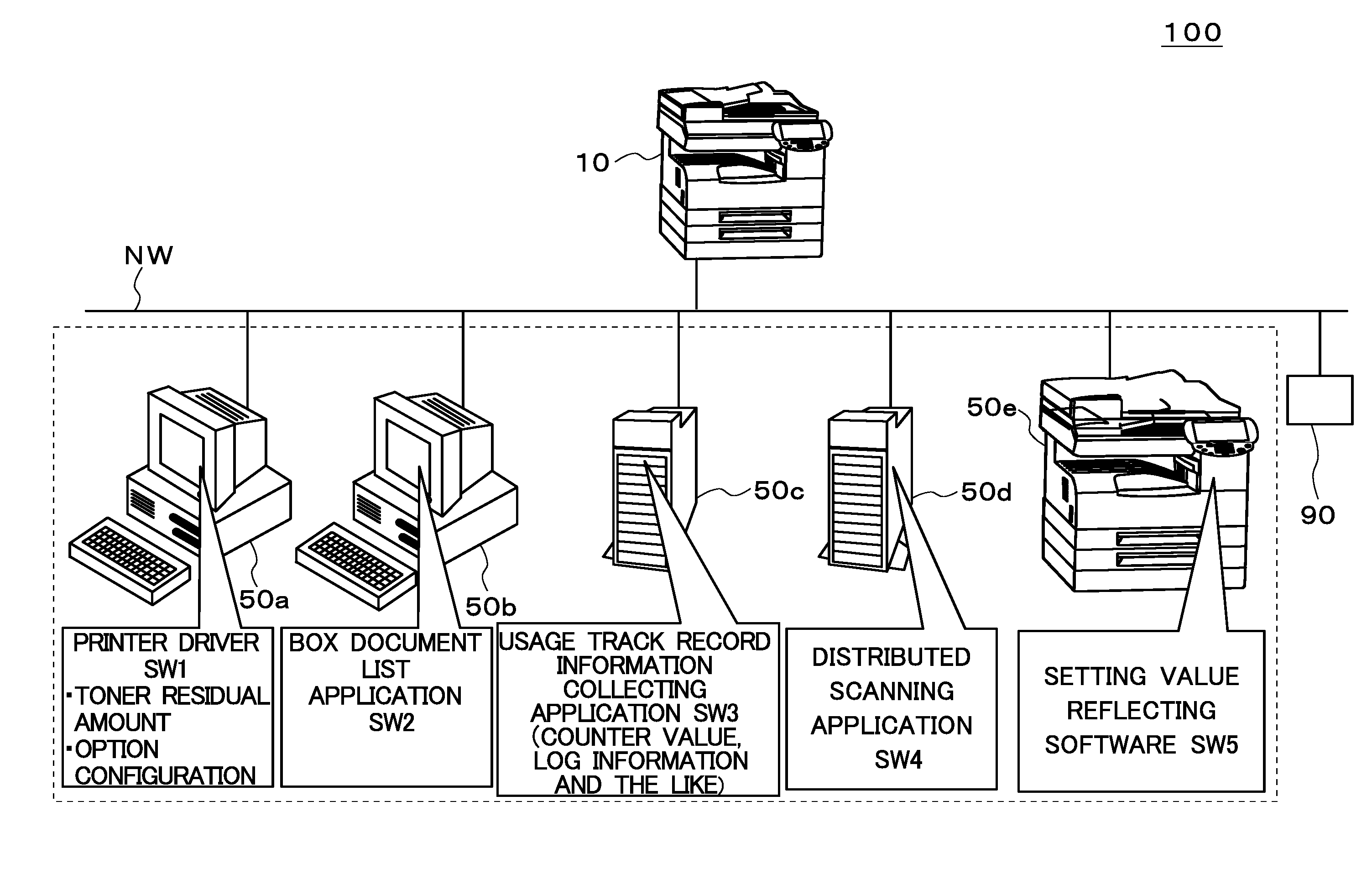
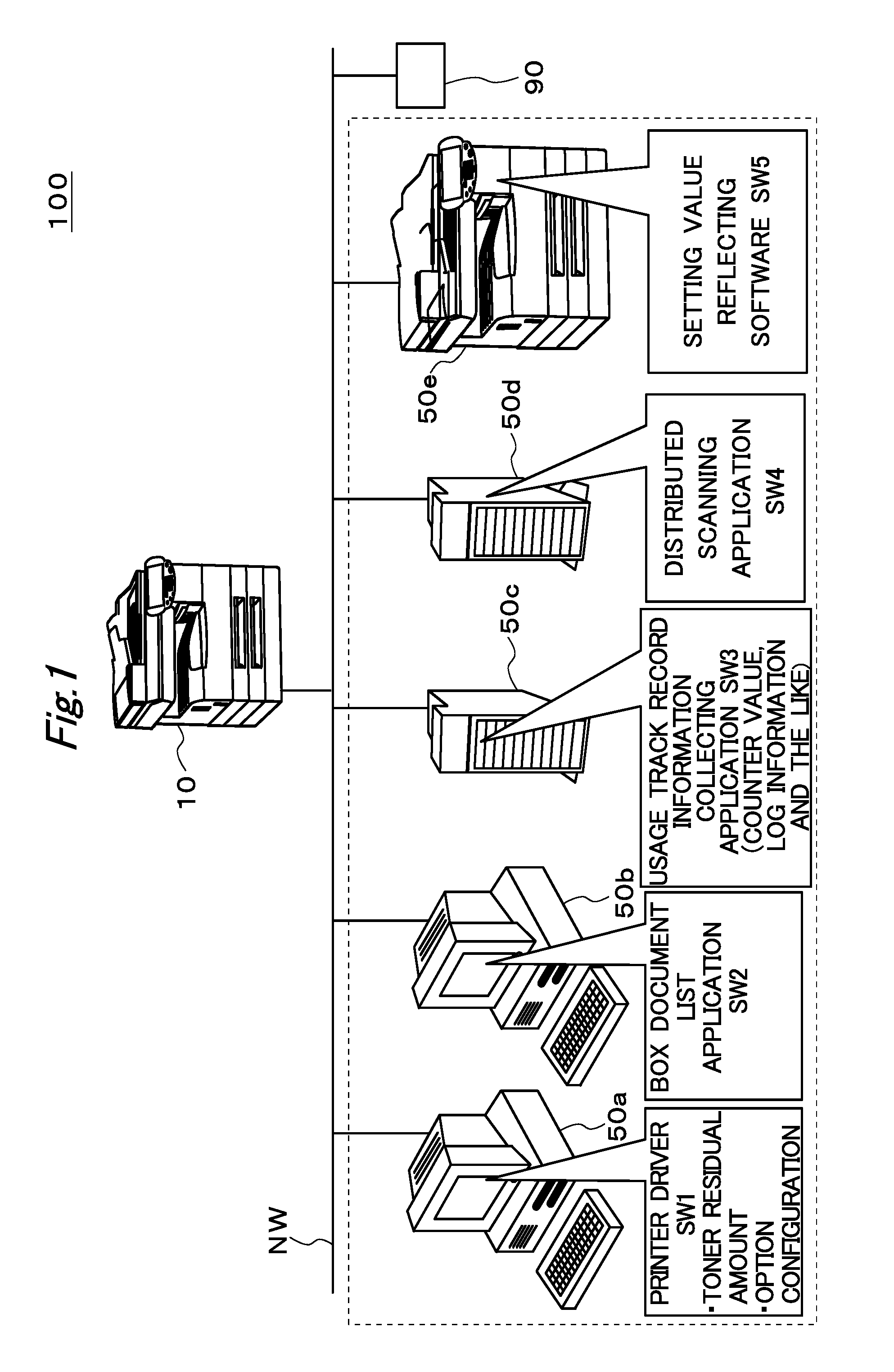
[0121]For example, in the above-described embodiment, the case (step S1 of FIG. 6) is illustrated where it is decided that the MFP 10 is to shift from the normal mode MD11 to the power saving mode MD12 when the condition that the command input to the MFP 10 is not given for the fixed time is established; however, the present invention is not limited to this. Specifically, the MFP 10 may shift to the power saving mode MD12 by a timer function. More specifically, the MFP 10 may be set to operate in the power saving mode MD12 for a predetermined period (as an example, a business unbusy time such as a time from 0 o'clock in the afternoon to 1 o'clock in the afternoon and a time from 8 o'clock in the afternoon to 8 o'clock in the following morning).

[0122]Moreover, in such a case, a notice on a scheduled start time and the like of the power saving mode MD12 may be issued in advance from the MF...

second modification example

Advance Notice of End Time of Power Saving Mode, and the Like

[0132]Moreover, the scheduled end time of the power saving mode MD12 may be used as follows. A description is made below of a modification example (also referred to as a second modification example) related to a using example of the scheduled end time of the power saving mode MD12. The second modification example is one further modified from the first modification example, and a description is made below mainly of different points from the first modification example.

[0133]Note that, in the above-described embodiment and the like, with regard to the print command output operation of the printer driver SW1, the case has been illustrated where the contact (communication) prohibiting operation in the cache mode MD52 is not applied thereto; however, in this second modification example, also with regard to the print command output operation of the printer driver SW1, the contact (communication) prohibiting operation in the cach...


PUM


Abstract

An image forming system includes: an image forming apparatus; and a linking apparatus that is linked with the image forming apparatus. The linking apparatus is operable in any of a plurality of modes including a first mode of contacting the image forming apparatus and executing a specific operation and a second mode of not contacting the image forming apparatus for a purpose of executing the specific operation. The image forming apparatus includes a mode shift command unit that, when the image forming apparatus shifts to a power saving mode, notifies the linking apparatus of a shift command indicating that the linking apparatus should be shifted to the second mode. Moreover, the linking apparatus includes: an operation mode control unit that shifts the linking apparatus to the second mode based on the shift command; and an access control unit that, after the shift to the second mode, prohibits the contact with the image forming apparatus, which is performed for the purpose of executing the specific operation.

Description

[0001]This application is based on Japanese Patent Application No. 2010-089179 filed on Apr. 8, 2010, the contents of which are hereby incorporated by reference.BACKGROUND OF THE INVENTION[0002]1. Field of the Invention[0003]The present invention relates to an image forming system and a technology related to the image forming system.[0004]2. Description of the Related Art[0005]In recent years, an image forming apparatus has been present, which is provided with a “sleep mode (power saving mode)” of restrictively supplying power only to a part of an apparatus in order to achieve a reduction of power consumption.[0006]Moreover, following the development of the network technology, a technology has been present, which is for transferring a variety of data between the image forming apparatus and another apparatus (also referred to as a linking apparatus) linked with the image forming apparatus as described above. For example, in printer driver software executed in a computer connected to ...

Claims


Application Information

Patent Timeline
IPC IPC(8): G06F15/00G06F3/12
CPCG06F3/1221G06F3/1229Y02B60/1271G06F3/1288G06K15/402G06F3/126Y02D10/00
Inventor KOBAYASHI, MINAKOAKITA, KATSUHIKOMINAMI, TAKESHIANEZAKI, KAZUYA
Owner KONICA MINOLTA BUSINESS TECH INC
Why Eureka
Try Eureka