Image forming apparatus

a technology of image forming apparatus and forming machine, which is applied in the direction of electrographic process apparatus, instruments, optics, etc., can solve the problems of abnormal images including color shift or uneven pitch on the output image, and the productivity of image formation in continuous printing operation is degraded, so as to achieve the effect of longer life and high productivity in continuous printing

Active Publication Date: 2011-10-13
RICOH KK
View PDF5 Cites 15 Cited by
  • Summary
  • Abstract
  • Description
  • Claims
  • Application Information

AI Technical Summary

Benefits of technology

[0012]This invention aims to solve the aforementioned problems, and provide a novel image forming apparatus capable of forming a quality image without color shift or uneven pitch on an output image ev...

Problems solved by technology

Such a separation operation saves wear and tear on the imaging section which is not used in the image formation, but with the disadvantage that productivity of the image formation in the continuous print operation is degraded.
However, since image ...

Method used


Image

  • Image forming apparatus
  • Image forming apparatus
  • Image forming apparatus

Examples


first embodiment

[0028]A first embodiment of the present invention will now be described with reference to FIGS. 1 through 11.

[0029]First, a configuration and operation of an entire image forming apparatus will be described with reference to FIGS. 1 through 3.

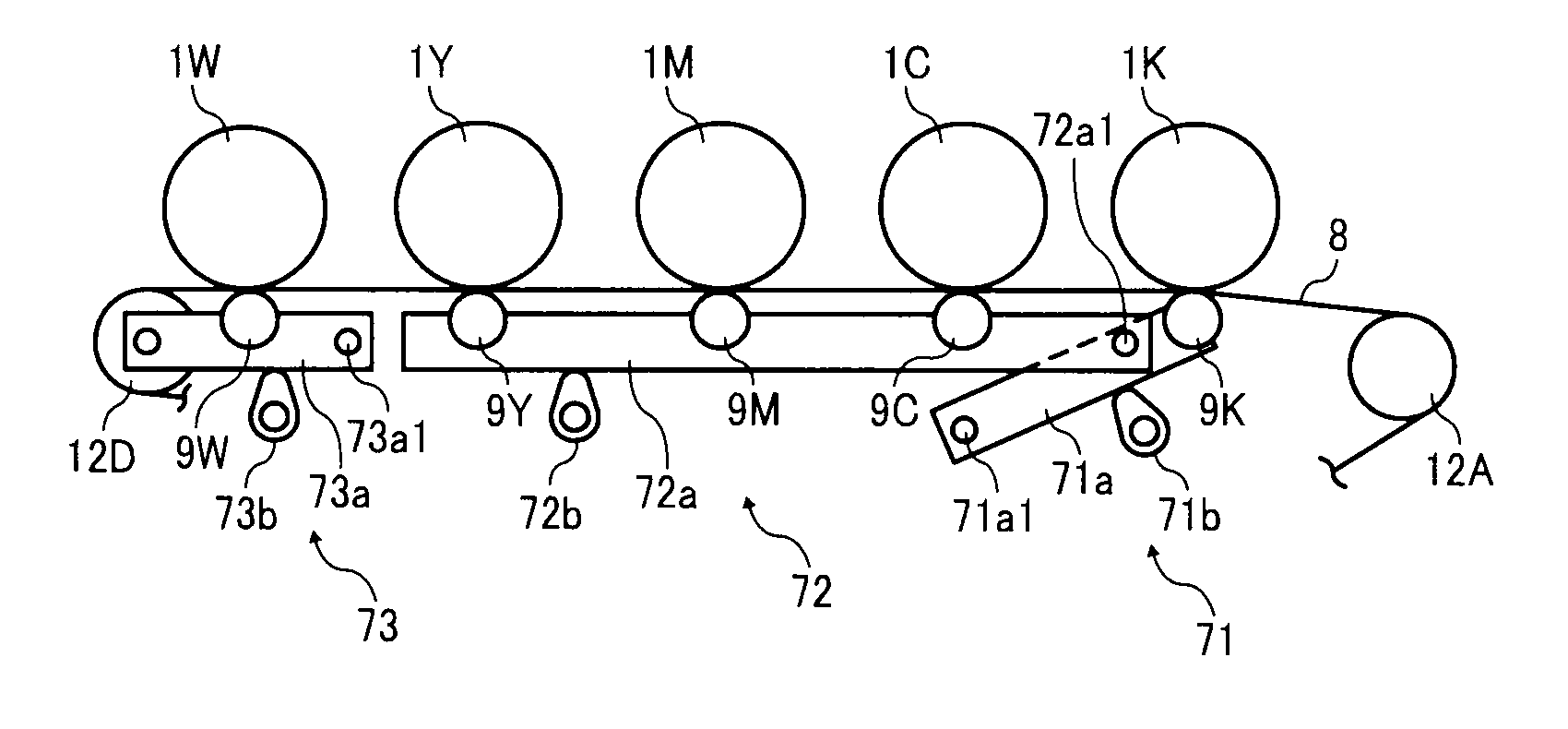
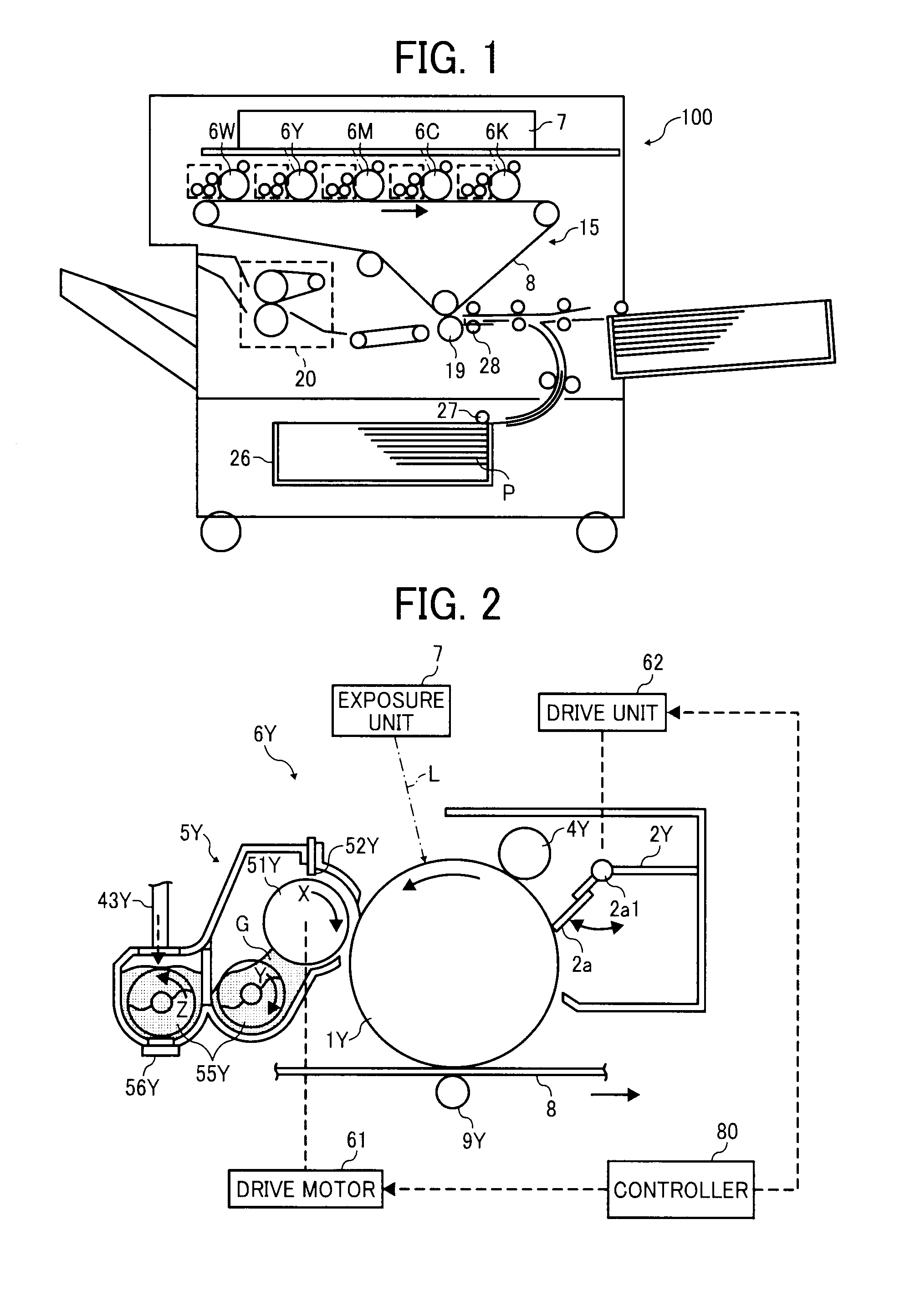
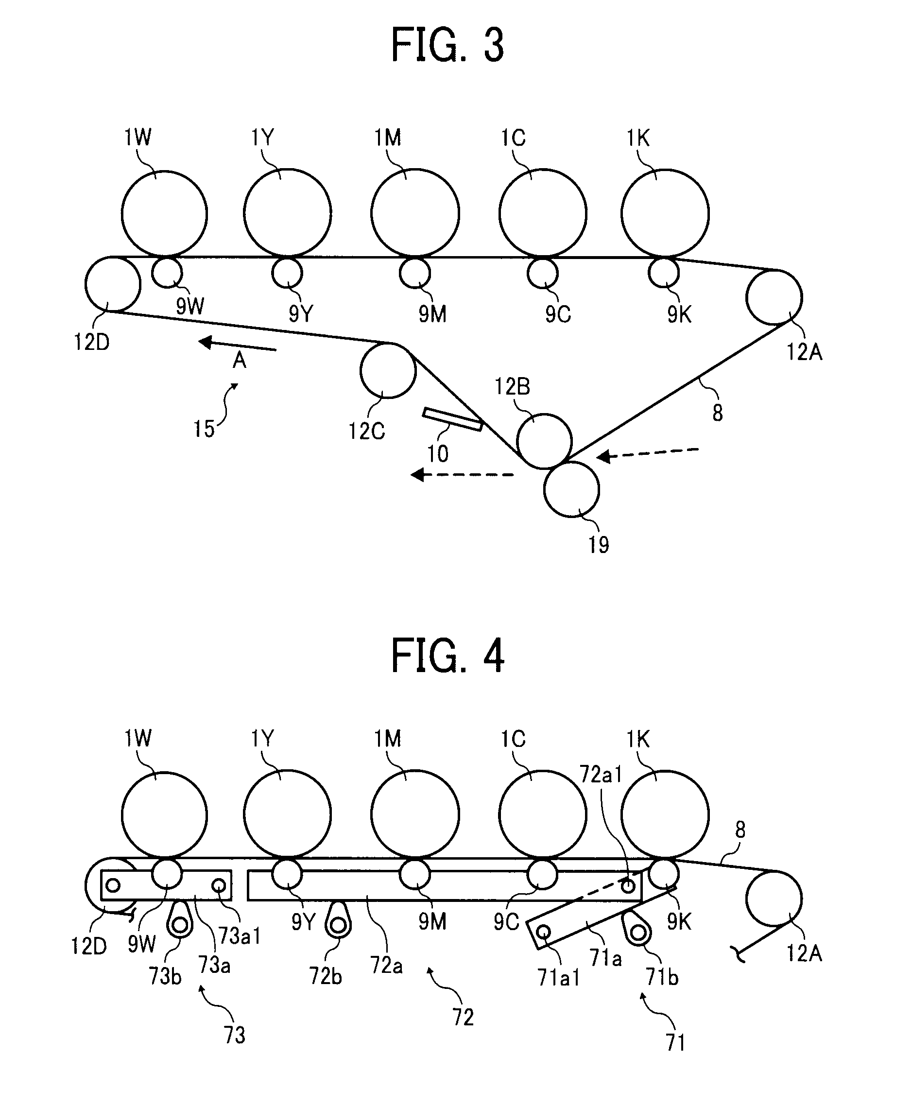
[0030]FIG. 1 is a configuration of the image forming apparatus serving as a copier. FIG. 2 is an enlarged view of the image forming section of the apparatus. FIG. 3 shows a diagram showing a portion in the proximity of an intermediate transfer belt 8.

[0031]As illustrated in FIG. 1, an intermediate transfer unit 15 or an intermediate transfer belt unit is disposed in the central portion of the main body of the image forming apparatus 100. The intermediate transfer unit 15 includes an intermediate transfer belt 8. An image forming section 6K for black toner, image forming sections 6Y, 6M, and 6C for color toner corresponding to three colors of yellow, magenta, and cyan, and an image forming section 6W for special toner are disposed in parallel an...


PUM


Abstract

An image forming apparatus includes a first image carrier forming a black toner image, a plurality of second image carriers forming a yellow, magenta, or cyan toner image, a third image carrier forming a special color toner image, and a transfer target member or an intermediate transfer belt. The apparatus further includes first and second detachment units. The first detachment unit detaches only the third image carrier from the transfer target member, and the second detachment unit detaches the second image carriers and the third image carrier. When switching from a special color image mode to either a normal color image mode or a monochrome image mode is performed during continuous printing of the recording media, the first detachment unit or the second detachment unit controls the detachment operation based on the number of recording media continuously printed by the normal color image mode or the monochrome image mode.

Description

CROSS-REFERENCE TO RELATED APPLICATIONS[0001]The present application claims priority from Japanese patent application numbers 2010-090452 and 2010-237028, filed on Apr. 9, 2010 and Oct. 22, 2010, respectively, the entire contents of which are incorporated by reference herein.BACKGROUND OF THE INVENTION[0002]1. Field of the Invention[0003]The present invention relates to an image forming apparatus such as a copier, printer, facsimile machine, or multifunctional apparatus combining two or more of the above functions, and in particular to an image forming apparatus employing a special color of toner.[0004]2. Description of the Related Art[0005]In image forming apparatuses such as copiers, printers, or facsimile machines, there is a conventionally known transfer technology in which special toner such as a transparent toner or white toner is used together with a plurality of color toners, and toner images formed of the plurality of color toners and the special color toner are superimpose...

Claims


Application Information

Patent Timeline
IPC IPC(8): G03G15/01
CPCG03G2215/0193G03G15/0131G03G15/0136
Inventor YOSHIDA, KEN
Owner RICOH KK
Why Eureka
Try Eureka