
Aluminium combustion power system

Active Publication Date: 2011-10-20
PENN STATE RES FOUND
View PDF4 Cites 18 Cited by
  • Summary
  • Abstract
  • Description
  • Claims
  • Application Information

AI Technical Summary

Benefits of technology

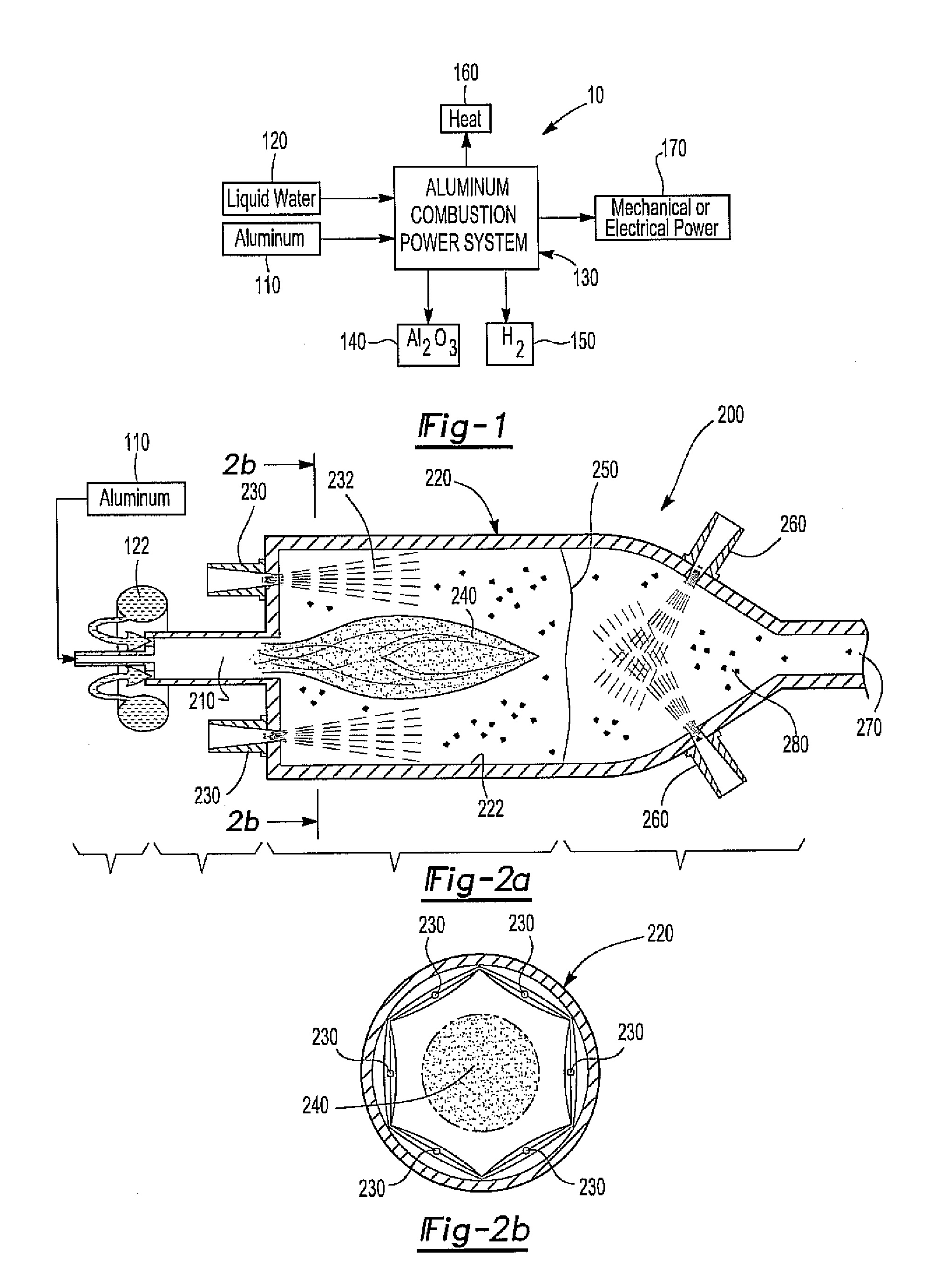
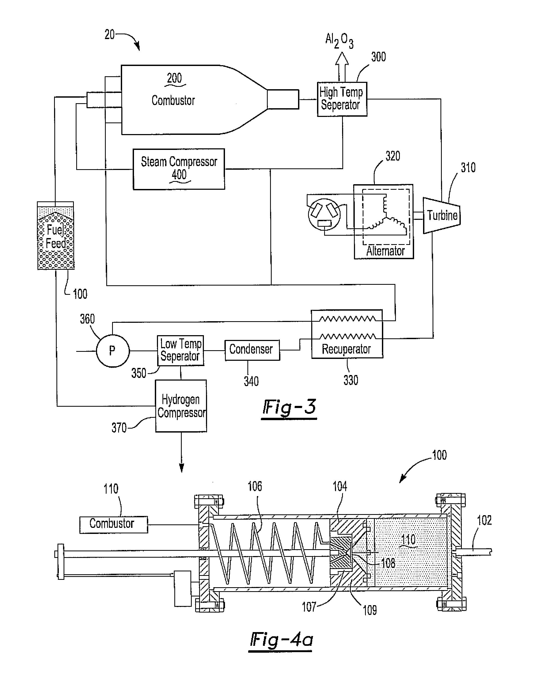
[0007]The combustor can have an inlet, an outlet, and a combustor wall, and the fuel feed system is operable to pump the fuel from a fuel tank to the combustor. The fuel injection system can mix steam that is fed back or recirculated from the combustor discharge via a small compressor or generated from a recuperator with the fuel and then spray the fuel and the steam mixture into the combustor. The water supply system can spray water into the combustor and the water can react with the aluminum powder to produce molten aluminum oxide droplets, heat, steam, and hydrogen. In addition, the water can solidify the molten aluminum oxide droplets before they contact the combustor wall and thereby prevent clogging of the combustor.
[0008]The aluminum powder can be coated, for example with a film of methysiloxane, such that the coated aluminum powder can be pumped through tubing having a length to diameter ratio of greater than 1000. In addition, the fuel feed system is operable to provide a steady flow of the coated aluminum powder at high pressure to the combustor. The mixture of aluminum powder and steam reacts with water in the combustor to produce the molten aluminum oxide droplets, heat, additional steam, and hydrogen. The water supply system can include a plurality of spray nozzles that can spray water into the combustor and cool the combustor wall. In addition, a high temperature separator downstream from the combustor can separate solidified aluminum oxide particles from an aluminum oxide particle-steam mixture that exits the outlet of the combustor. In this manner, steam without harmful and / or erosive aluminum oxide particles can be provided to a steam turbine to produce electrical and / or mechanical power.

Problems solved by technology

In addition, the use of batteries has exhibited limited success, however the energy density of battery powered systems has been less than desirable.
with the products of this reaction exhibiting temperatures up to 3800° F. However, such temperatures and products have heretofore proven to be impractical for power systems that can provide a steady and sustained flow of energy.
Therefore, even though the above chemical reaction is extremely energy favorable, the use of aluminum as a fuel to provide a reliable source of energy has proven evasive.

Method used


Image

  • Aluminium combustion power system
  • Aluminium combustion power system
  • Aluminium combustion power system

Examples


Embodiment Construction

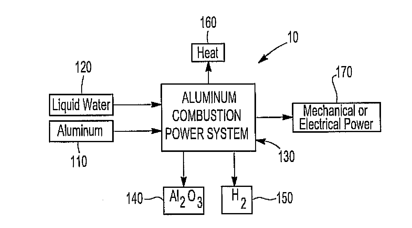
[0016]The present invention provides an engine that reacts aluminum with water to produce electrical and / or mechanical power. As such, the present invention has use as a power source.

[0017]The power system can include a combustor that is operable to accept aluminum powder mixed with steam. In addition, the combustor can have water sprayed thereinto, the water reacting with the aluminum powder to form molten aluminum oxide droplets, steam, heat, and hydrogen. In addition, sufficient water can be provided to the combustor such that excess steam is provided and used to drive / power a steam turbine as is known to those skilled in the art.

[0018]The aluminum powder can be coated such that it flows like a liquid and can be provided from a fuel container to the combustor using a fuel line having a length to diameter ratio of greater than 1000. In addition, the aluminum powder can be mixed with the steam prior to entering the combustor such that the mixture expands like a gas upon entering a ...


PUM


Abstract

An engine that oxidizes aluminum with water to produce electrical and / or mechanical power. The engine can include a fuel made at least partly from aluminum powder that flows like liquid under high pressure. The engine can also include a steam supply system, a combustor, a fuel feed system, a fuel injection system, and a water supply system.

Description

CROSS-REFERENCE TO RELATED APPLICATIONS[0001]This application claims priority of U.S. Provisional Patent Application Ser. No. 61 / 325,995 filed Apr. 20, 2010, which is incorporated herein by reference in its entirety.GOVERNMENT INTEREST[0002]This invention was made with government support under Contract No. N0024-02-6604 / 0031 awarded by the Defense Advanced Research Projects Agency. The Government has certain rights in the invention.FIELD OF THE INVENTION[0003]The present invention is related to an aluminum combustion power system, and in particular an aluminum combustion power system that reacts water with aluminum powder to produce molten aluminum oxide droplets, heat, steam, and hydrogen.BACKGROUND OF THE INVENTION[0004]The use of internal combustion engines, batteries, jet propulsion, and the like to provide power to underwater vehicles is known. In addition, the use of batteries has exhibited limited success, however the energy density of battery powered systems has been less th...

Claims


Application Information

Patent Timeline
IPC IPC(8): F01K13/00F01K23/06
CPCF01K21/04
Inventor CAWLEY, THOMASLOWERY, BRIANMILLER, TIMOTHY F.HERR, JOHNKLANCHAR, MARTINKIELY, DANIEL H.
Owner PENN STATE RES FOUND
Learn More