
Ultrasonically controllable grease dispensing tool

a technology of ultrasonic energy and grease, applied in the direction of manual lubrication, instruments, processing detected response signals, etc., can solve the problems of generating a higher ultrasonic energy level, affecting the accuracy of the diagnostic results, so as to reduce the liability of the maintenance company for failures subsequent to the test, and the diagnostic results can be even more precis

Active Publication Date: 2011-10-20
U E SYST
View PDF27 Cites 37 Cited by
  • Summary
  • Abstract
  • Description
  • Claims
  • Application Information

AI Technical Summary

Benefits of technology

[0018]The lubrication tool would further be able to listen to the bearing ultrasonically while lubricating it, thus ensuring the proper amount of grease is added. In particular, as the lubrication is added the friction forces will be reduced, which in turn will lead to a reduction in the amplitude of the ultrasonic signal.
[0031]The storage of heterodyned audio, images and spectrums can be on removable media cards such as an SD or other removable media type. This allows information to be easily uploaded to a central computer or downloaded to the portable hand-held ultrasonic detector.

Problems solved by technology

Additionally, faulty devices, such as bearings, generate a higher level of ultrasonic energy than do good bearings and thus, this condition can also be detected.
However, a major reason for bearing failure is improper lubrication, not just a failure to lubricate.
In particular, over lubrication can be a problem.
Since acoustic energy created by faulty bearings is detectable in both the audible and ultrasonic frequency ranges, generally in the range of 28 to 40 kHz, in noisy audible environments, the audible components are too difficult to unaided humans to detect.
However, the detector disclosed in Peacock does not process the detected signal to produce an audible response, nor does it provide for signal attenuation after the initial pre-amplification stage.
However, it is extremely difficult for a person to discern with their ears the differences between inputs that are representative of bearings just beginning to deteriorate and those which are more seriously deteriorated.
The use of the human ear is a highly unreliable way in which to predict faults.
The difficulty is that the motors with bearings under test can be spread out over large distances.
Complete failure of the bearings can leave a motor inoperable for a period of time.
In some instances, it is very detrimental to have a motor out of service for even a small amount of time, e.g., a cooling pump.

Method used


Image

  • Ultrasonically controllable grease dispensing tool
  • Ultrasonically controllable grease dispensing tool
  • Ultrasonically controllable grease dispensing tool

Examples


Embodiment Construction

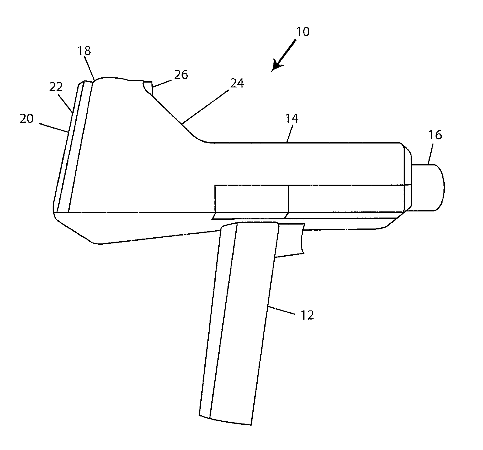
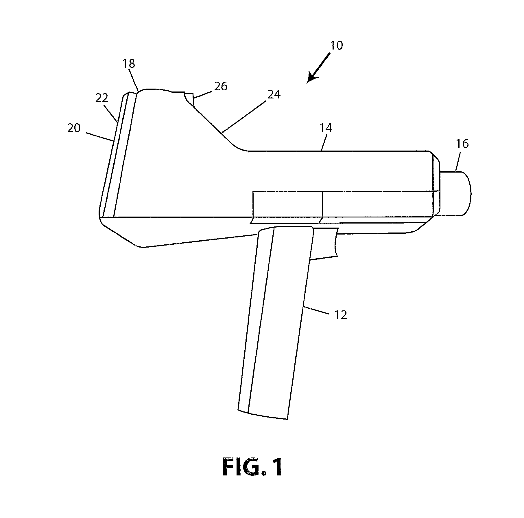
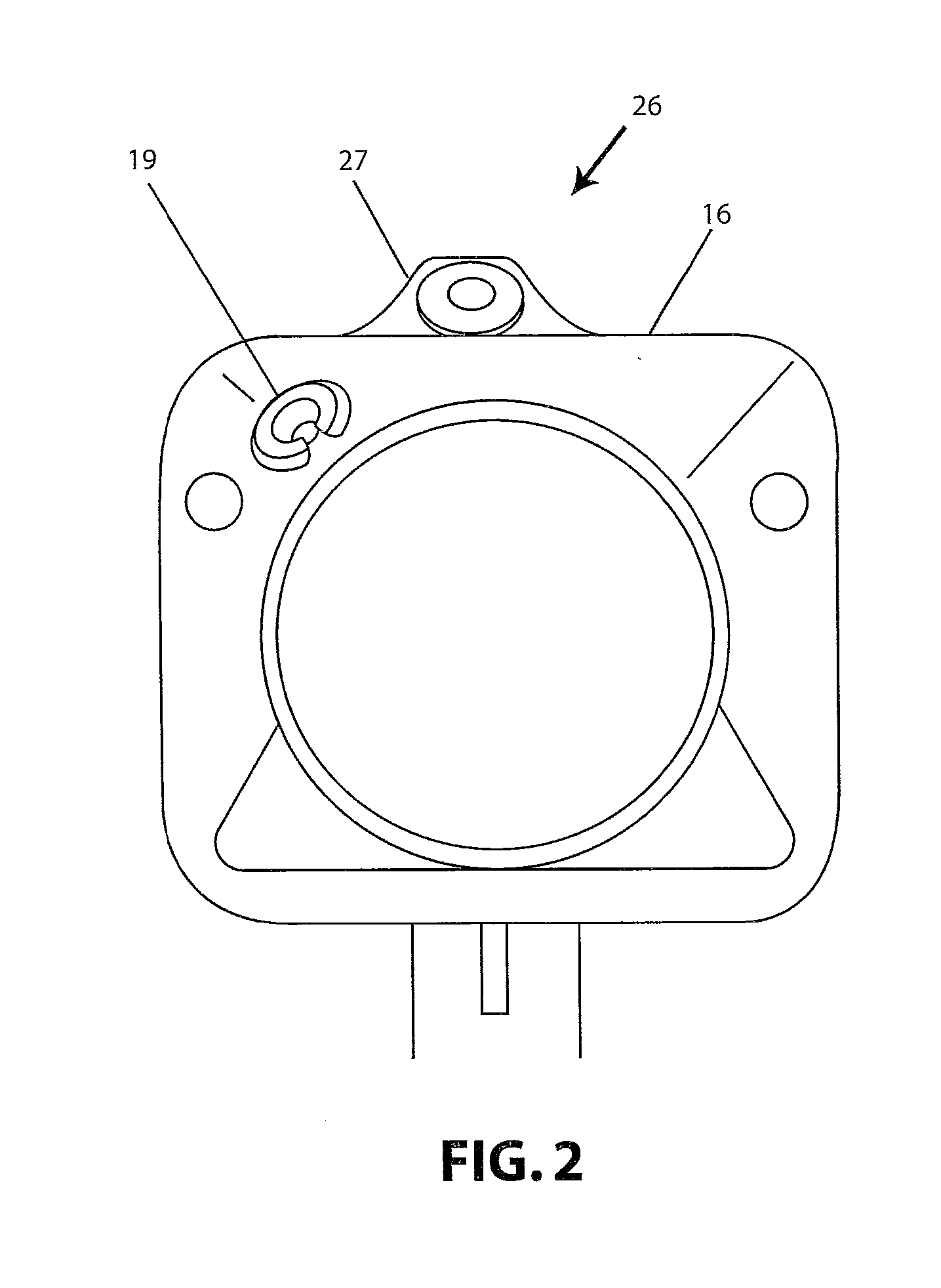
[0041]Referring now to the drawings wherein like references numerals designate corresponding parts throughout the several views. In FIG. 1 the ultrasonic detector 206 is connected to the lubrication tool 200 (such as a grease gun), which has a neck 202 and a grease fitting adaptor 204. The ultrasonic circuitry is located in housing 208 which is attached to the body of grease gun 200 by, for example, Velcro® straps 212. Alternatively, housing 208 can be attached to grease gun 200 by clips, wire ties, or any other suitable means, such as welding and adhesives.

[0042]The ultrasonic transducer(s) is contained within housing 210 and is connected to the ultrasonic circuitry by wire 209. Transducer housing 210 attaches to grease gun 200 along neck 202 near grease fitting adaptor 204. However, the transducer can be attached by any other mechanism that places it in acoustical contact with grease fitting adaptor 204 or neck 202. Other ways to attach the transducer to the grease gun include a s...


PUM


Abstract

A lubrication dispensing apparatus for lubricating a device with moving parts includes a lubricant reservoir, a lubricant dispenser for dispensing lubricant from the lubricant reservoir, an ultrasonic detection module which detects the amplitude of ultrasonic energy emitted by said device when its parts are moving and produces an signal related thereto, and a control module which analyzes the amplitude of the signal from the ultrasonic detection module and, in response to a lubricate signal, causes the lubricant dispenser to automatically dispense lubricant onto the moving parts of the device until the signal from the ultrasonic detector indicates that the ultrasonic energy produced by the device has decreased to a particular level. The control module includes a programmed processor and a storage memory. The memory stores as a base value the value of the detected amplitude of ultrasonic energy when the device is operating properly. After receiving a signal to lubricate the device, the processor causes the dispenser to start the flow of lubricant to the device, compares the signal from the ultrasonic detection module when the parts are moving to the base value, and causes the dispenser to cease the flow of lubricant when the signal substantially decreases.

Description

CROSS-REFERENCE TO RELATED APPLICATION[0001]This application is related to and claims the benefit of U.S. Provisional Patent Application Ser. No. 61 / 325,194 filed Apr. 16, 2010 and entitled ON-BOARD ULTRASONIC FREQUENCY SPECTRUM AND IMAGE GENERATION, the contents of which are incorporated herein by reference in their entirety. This application is also related to U.S. patent application Ser. No. [Attorney Docket No. 7415 / 0893-US1] entitled ON-BOARD ULTRASONIC FREQUENCY SPECTRUM AND IMAGE GENERATION filed concurrently herewith.BACKGROUND OF THE INVENTION[0002]a. Field of the Invention[0003]The invention relates generally to a controllable grease dispersion tool for use in lubricating the bearings, gears or transmission of a device or machine and, more particularly, to a portable grease dispersion tool incorporating a portable ultrasonic detector to detect the condition of motor bearings, gears or transmission as lubrication is applied.[0004]b. Description of the Related Art[0005]Ultra...

Claims


Application Information

Patent Timeline
IPC IPC(8): F16N29/02F16N3/12F16N3/00
CPCG01M13/028G01M3/24G01M7/00G01H3/125G01M13/045G01N29/46G01B17/00G01M13/04
Inventor GOODMAN, MARK A.BISHOP, WILLIAMMOHR, GARY
Owner U E SYST
Learn More