Organic Light-Emitting Diode Device with High Color Rendering

Active Publication Date: 2011-10-20
NATIONAL TSING HUA UNIVERSITY
View PDF2 Cites 3 Cited by
  • Summary
  • Abstract
  • Description
  • Claims
  • Application Information

AI Technical Summary

Benefits of technology

[0010]The major objective of the present invention is to provide the OLED device with high color rendering, which employs the characteristic of the plural white light emitting layers having the complementary spectra so as to achieve the effect of high color rendering and decrease the number of components and the production cost.
[0011]Another objective of the present invention is to provide the OLED device with high color rendering, which employs the characteristic of two layers of white light emitting layers having the complementary spectra so as to achieve the effect of high color rendering and decrease the number of components and the production cost.
[0012]Consequently, the present invention provides an organic light-emitting diode (OLED) device with high color rendering comprising: a base plate; a first conductive layer being disposed on the base plate; a plurality of white light emitting layers being disposed on the first conductive layer, wherein the spectra of the plurality of white light emitting layers possess characteristics of complementarities so as to enhance the color rendering of the emitted white light; and a second conductive layer being disposed on the plurality of white light emitting layers.
[0013]Furthermore, the present invention provides another organic light-emitting diode (OLED) device with high color rendering comprising: a base plate; a first conductive layer being disposed on the base plate; a first white light emitting layer being disposed on the first conductive layer and having a first spectrum; a second white light emitting layer being disposed on the first white light emitting layer and having a second spectrum, wherein the first spectrum and the second spectrum are complementary so as to increase the color rendering of the emitted white light; and a second conductive layer being disposed on the second white light emitting layer.

Problems solved by technology

The lower value of the CRI, the more differences between the above revealed colors, and the colors presented by the artificial light source lose more fidelity.
However, due to the foregoing conventional technique has to combine several kinds of OLED devices emitting different colors to achieve the effect of high color rendering, then it not only consumes more production cost but also increases the dimension of the products.

Method used


Image

  • Organic Light-Emitting Diode Device with High Color Rendering
  • Organic Light-Emitting Diode Device with High Color Rendering
  • Organic Light-Emitting Diode Device with High Color Rendering

Examples


Embodiment Construction

[0022]To achieve the foregoing objectives and effects, the inventors combine more than two layers of white light emitting layers and employ the characteristic of complementary spectra, thus achieving an OLED device with high color rendering of the present invention. Hereinafter, the OLED device with high color rendering according to a first preferred embodiment, a second preferred embodiment and a third preferred embodiment of the present invention will be described in detail for illustrating the structural features and principles of the present invention.

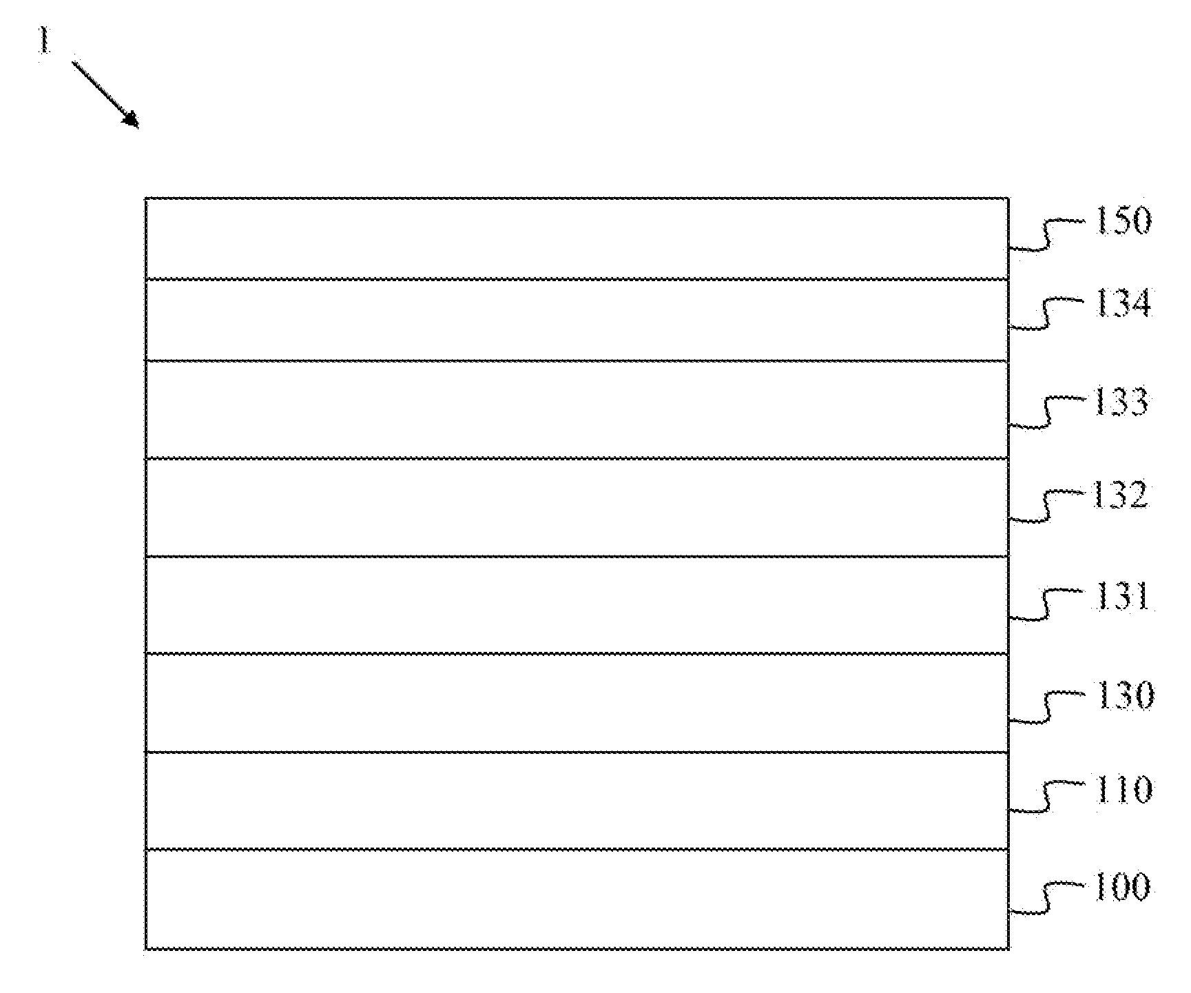
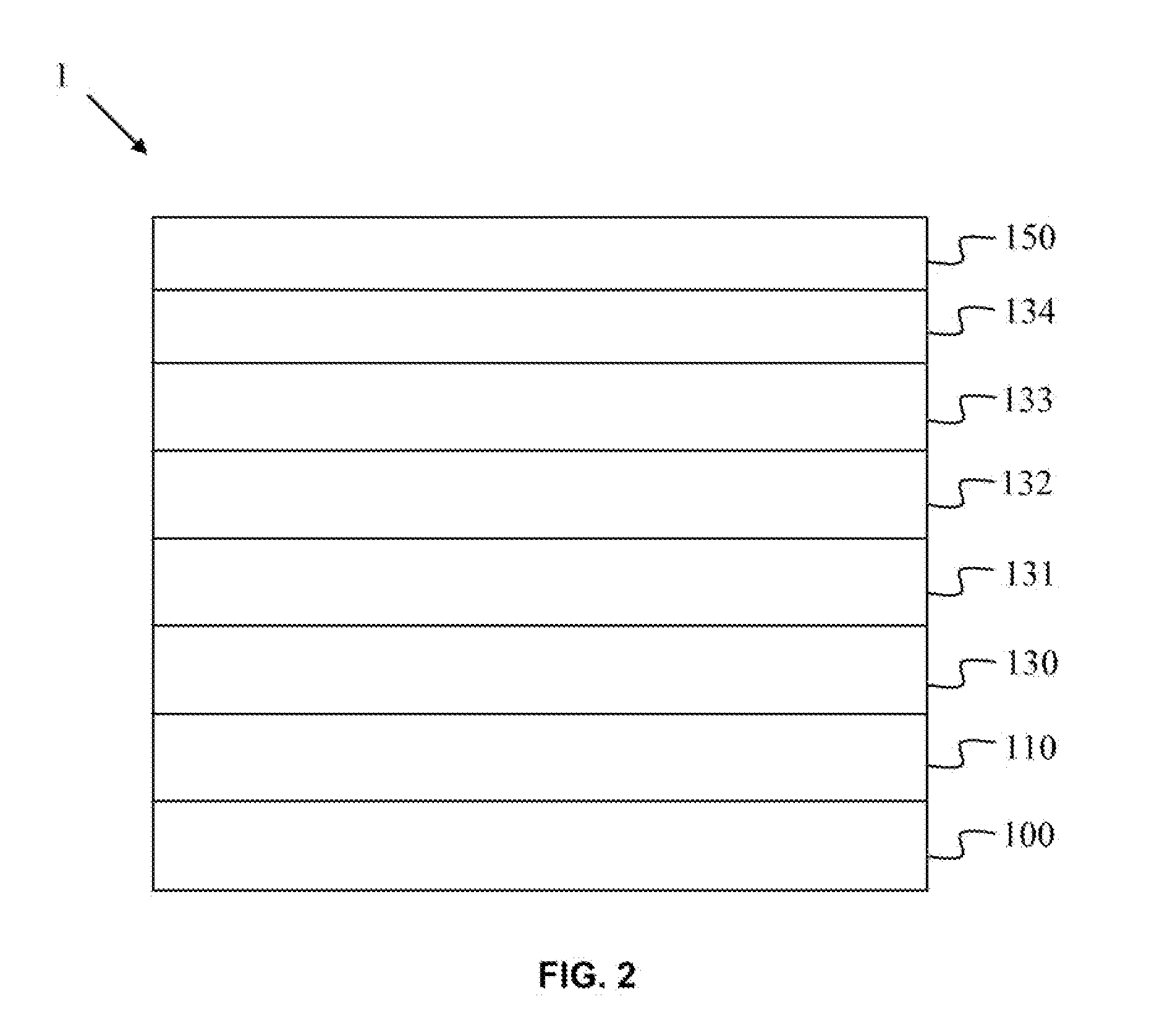
[0023]Referring to FIG. 2, a cross-sectional diagram of the OLED device with high color rendering according to the first preferred embodiment of the present invention is illustrated. The OLED device 1 of the present invention includes: a base plate 100, which is a glass substrate; a first conductive layer 110 being disposed on the base plate 100 and being an anode, wherein the first conductive layer 110 is made of indium tin oxide ...


PUM


Abstract

The present invention discloses an organic light-emitting diode (OLED) device with high color rendering comprising a base plate, a first conductive layer, a plurality of white light emitting layers, and a second conductive layer, wherein the spectra of the white light emitting layers possess characteristics of complementarities so as to enhance the color rendering of the emitted white light, and at least one carrier regulating layer is selectively disposed between every two white light emitting layers so as to increase the emitting efficiency and color rendering.

Description

BACKGROUND OF THE INVENTION[0001]1. Field of the Invention[0002]The present invention relates to an organic light-emitting diode (OLED) device, and more particularly to an OLED device comprising a plurality of white light emitting layers with complementary spectra so as to enhance the color rendering of the emitted white light.[0003]2. Description of the Prior Art[0004]An organic electro-luminescence display (Organic EL Display), also known as an organic light emitting diode (OLED), was invented by C. W. Tang and S. A. VanSlyk et al. of Eastman Kodak Company in 1987 and manufactured by a vacuum evaporation method. A hole transporting material and an electron counterpart are respectively deposited on a transparent indium tin oxide (abbreviated as ITO) glass, and then a metal electrode is vapor-deposited thereon to form the self-luminescent OLED apparatus. Due to high brightness, fast response speed, light weight, compactness, true color, no difference in viewing angles, no need of li...

Claims


Application Information

Patent Timeline
IPC IPC(8): H01L33/40
CPCH01L51/5016H01L51/5044H01L51/504H10K50/131H10K50/11H10K2101/10H10K50/13
Inventor JOU, JWO-HUEILIN, CHUN-JEN
Owner NATIONAL TSING HUA UNIVERSITY
Why Eureka
Try Eureka