
Measurement arrangement having a calibration substrate and electronic circuit

a technology of electronic circuit and measurement arrangement, which is applied in the direction of measuring devices, resistance/reactance/impedence, instruments, etc., can solve the problem that the non-destructive measurement of embedded devices under test (duts) can only be carried out with great effor

Active Publication Date: 2011-10-20
ROSENBERGER HOCHFREQUENZTECHNIK GMBH & CO KG
View PDF3 Cites 8 Cited by
  • Summary
  • Abstract
  • Description
  • Claims
  • Application Information

AI Technical Summary

Benefits of technology

[0017]In a fourth aspect, the present invention is directed to a method for determining scattering parameters of an electrical device under test (DUT) having one or more electronic components that are electrically connected to one another, with a vector network analyzer, wherein the electrical device under test includes, and is embedded within, an electronic circuit, wherein at least one port of the vector network analyzer is electrically connected to a calibration substrate which comprises at least one calibration standard, and the vector network analyzer is calibrated, wherein subsequently the calibration substrate is disconnected from the vector network analyzer and the at least one port is electrically connected to an electrical contact point of the electronic circuit, such that the at least one port of the vector network analyzer is electrically connected to ...

Problems solved by technology

The disadvantage of vector network analysis is that non-destructive measurement of embedded devices under test (DUTs) can only be carried out with great effort, since for each measurement of an embedded DUT, the electrical periphery must also be taken into account during the calibration.

Method used


Image

  • Measurement arrangement having a calibration substrate and electronic circuit
  • Measurement arrangement having a calibration substrate and electronic circuit
  • Measurement arrangement having a calibration substrate and electronic circuit

Examples


Embodiment Construction

)

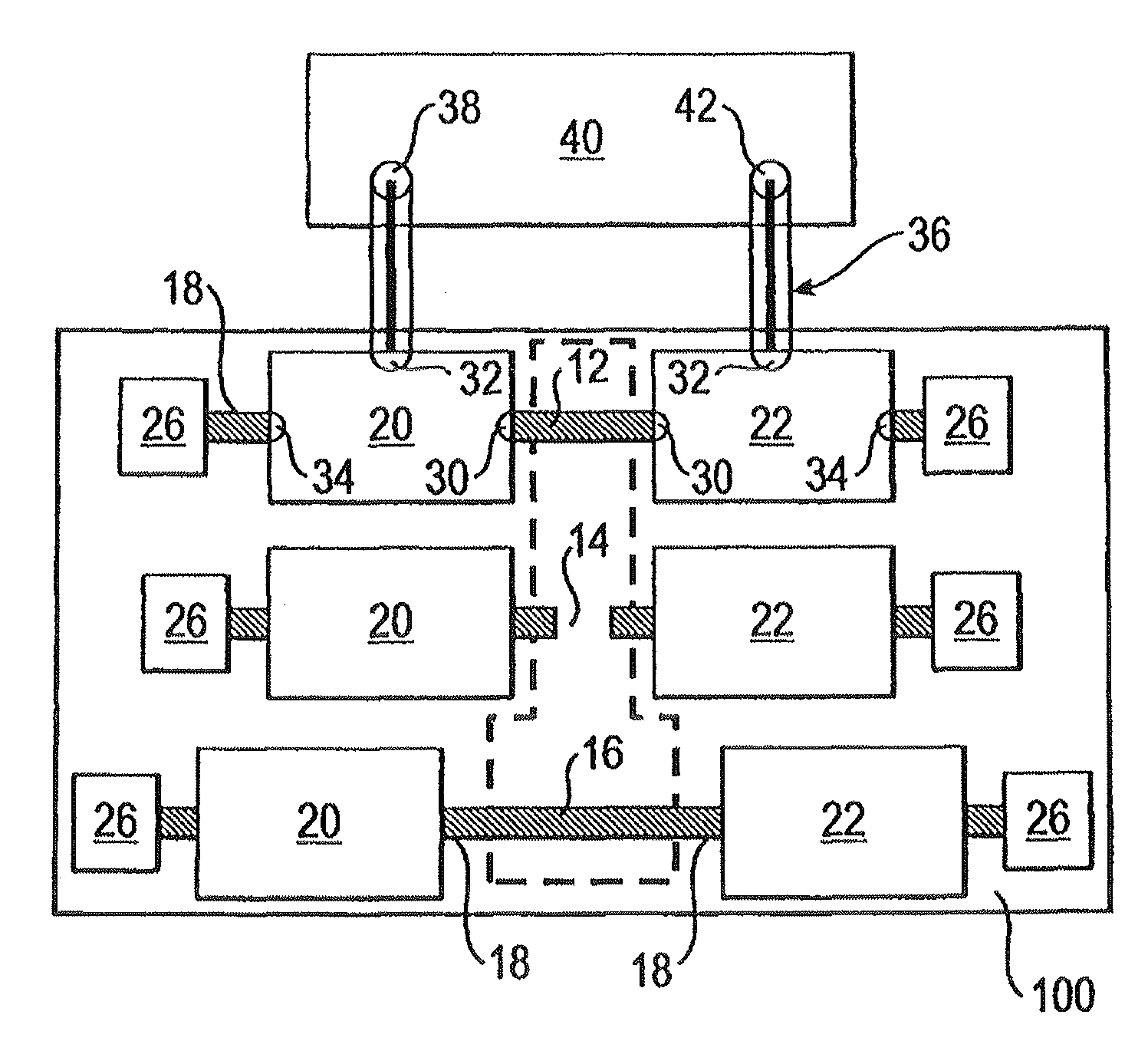
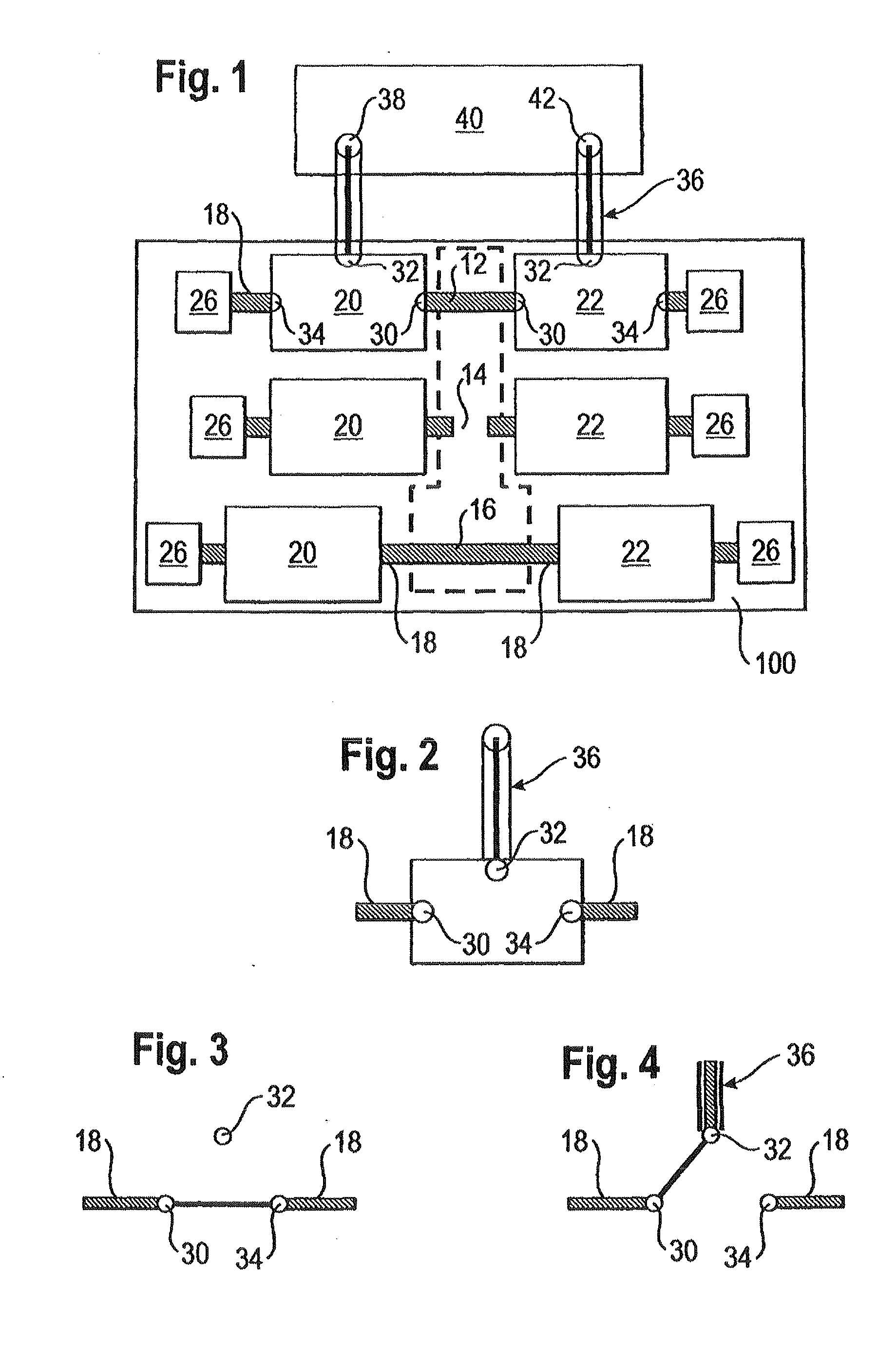
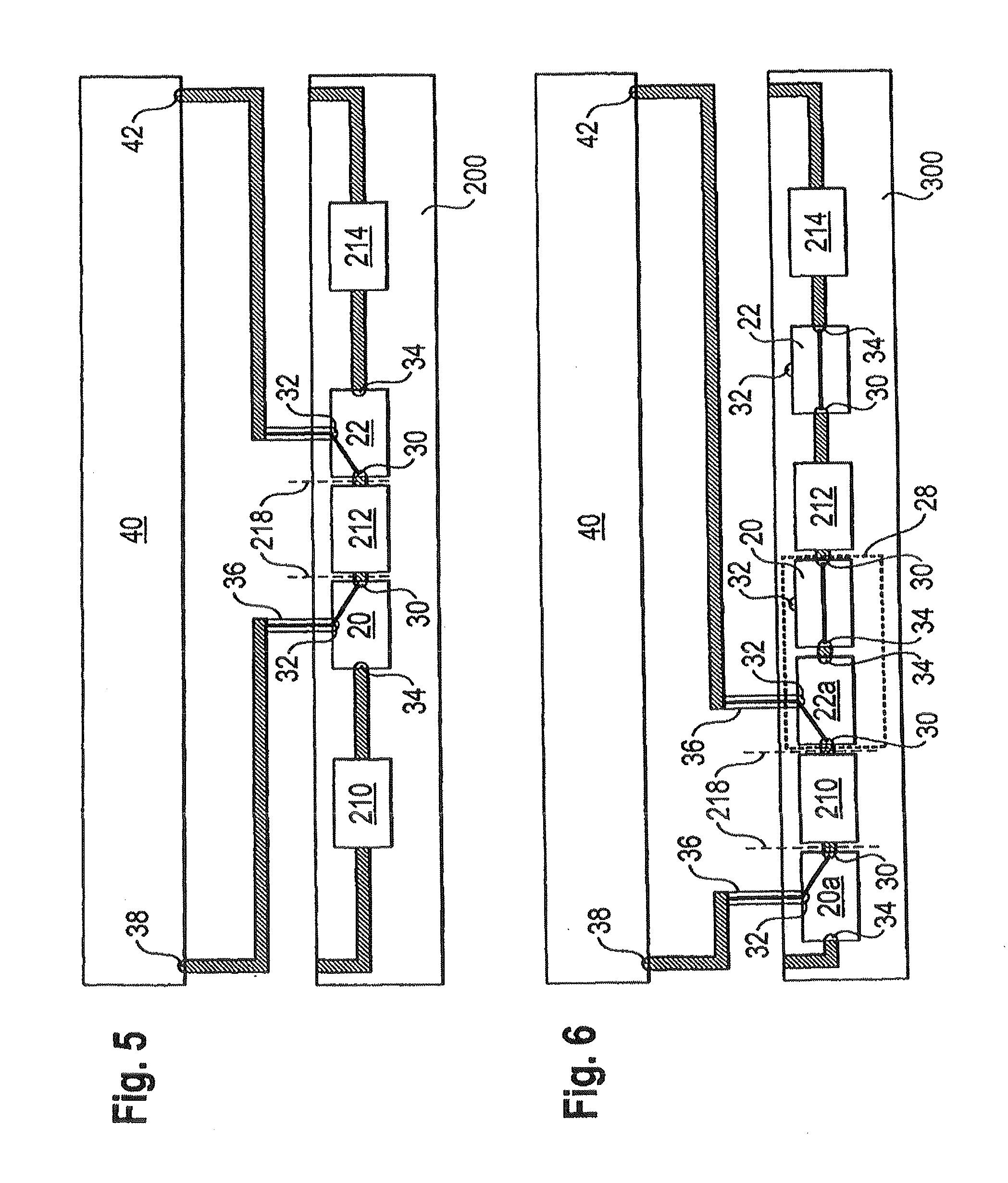
[0033]In describing the preferred embodiment of the present invention, reference will be made herein to FIGS. 1-11 of the drawings in which like numerals refer to like features of the invention.

[0034]In a calibration substrate of the aforementioned type, it is provided according to the invention that at least one electrical connection point of at least one calibration standard is configured with a switch, wherein the switch comprises one first electrical contact which is electrically connected to an electrical connection point of the calibration standard, a second electrical contact which is configured for electrically connecting to a measurement port of the vector network analyzer, and a third electrical contact, wherein the switch is configured such that with the second electrical contact free and electrically connected to nothing, the switch makes an electrical connection between the first and the third electrical contacts, wherein an electrical connection between the second and...


PUM


Abstract

A calibration substrate having at least one calibration standard with at least two electrical connection points, each for one measurement gate of a vector network analyzer. At least one electrical connection point is formed of at least one calibration standard having a switch, wherein the switch has a first electrical contact electrically connected to an electrical connection point of the calibration standard, a second electrical contact designed for electrically connecting to a measurement gate of the vector network analyzer, and a third electrical contact, wherein the switch is designed such that an electrical contact is established either between the first and third electrical contact or between the first and second electrical contact.

Description

[0001]This application is a National Stage filing based on PCT / EP2009 / 007009, filed Sep. 29, 2009, and which claims priority to German Patent Application No. DE 20 2008 013 687.3, filed Oct. 15, 2008.BACKGROUND OF THE INVENTION[0002]1. Field of the Invention[0003]The present invention relates to a calibration substrate having at least one calibration standard, comprising at least two electrical connection points, each for one measurement port of a vector network analyzer. The invention also relates to an electronic circuit with at least one electrical device under test (DUT) embedded in the electronic circuit, having electrical contact points which are electrically connected to the electronic circuit. The invention further relates to a measurement arrangement comprising the calibration substrate and the electronic circuit. The invention further relates to a method for determining scattering parameters of an electrical device under test (DUT), which comprises one or more electronic c...

Claims


Application Information

Patent Timeline
IPC IPC(8): G01R35/04
CPCG01R27/32G01R35/005G01R31/00G01R1/0416G01D18/00G01R27/28G01R31/28G01R35/00
Inventor ZELDER, THOMASGECK, BERND
Owner ROSENBERGER HOCHFREQUENZTECHNIK GMBH & CO KG
Learn More