Touch panel device

a touch panel and capacitive technology, applied in the field of capacitive touch panel devices, can solve the problems of increasing the length of the electrodes, affecting the performance of the panel, so as to increase the stiffness of the back plate, increase the resistance of the panel main body against deformation, and increase the length of the lead wires extending along the electro-conductive back plate

Inactive Publication Date: 2011-10-20
PANASONIC CORP
View PDF0 Cites 32 Cited by
  • Summary
  • Abstract
  • Description
  • Claims
  • Application Information

AI Technical Summary

Benefits of technology

[0008]In view of such problems of the prior art, a primary object of the present invention is to provide a touch panel device that can reduce the induction noises induced in the reception electrodes owing to the drive signal conducted through lead wires leading to the transmission electrodes.
[0009]A second object of the present invention is to provide a touch panel device that can minimize the unevenness in the positional distribution of the sensitivity of touch position detection owing to the variations in the lengths of the lead wires leading to the transmission electrodes.

Problems solved by technology

In such cases, as the electrodes may function as aerial antennas, interferences from external electromagnetic noises may become a problem.
However, as the mutual capacitive type touch panel device is susceptible to external noises as it is designed to detect a touch position by detecting an extremely small current generated in the reception electrode, and therefore involves a high impedance.
In particular, as the length of the electrodes is increased owing to the increase in the size of the touch panel device, the problem of external noises become even more acute.
As a result, the electric current of the drive signal that is conducted by the lead wires to be applied to the transmission electrodes may induce an undesirably high induction noises in the reception electrodes.
The induction noises that are generated in the reception electrodes caused by the electric current conducted by the lead wires cannot be effectively removed by the conventional arrangement.

Method used


Image

  • Touch panel device
  • Touch panel device
  • Touch panel device

Examples


Embodiment Construction

)

[0051]Now the present invention is described in the following in more detail in terms of concrete embodiments with reference to the appended drawings.

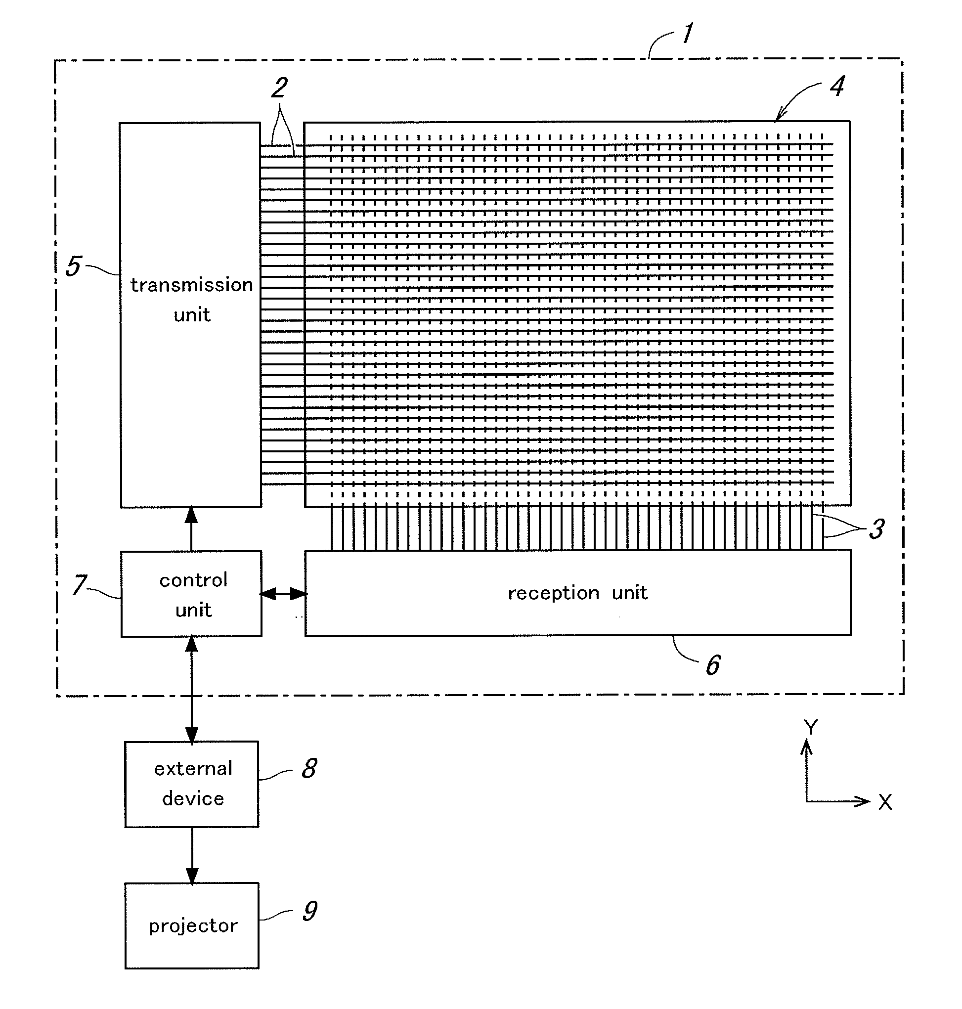
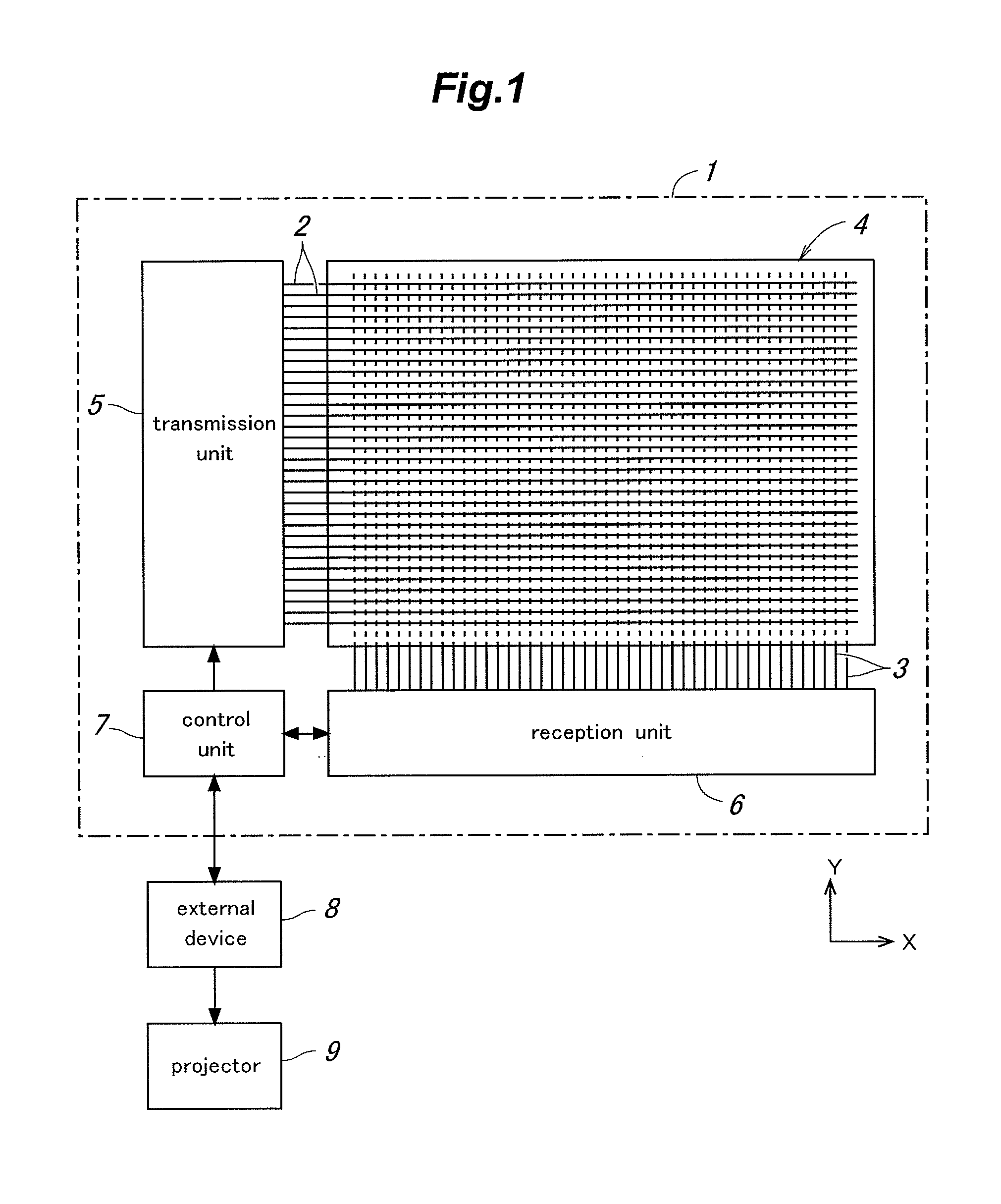
[0052]FIG. 1 is a diagram showing the overall structure of a touch panel device embodying the present invention. This touch panel device 1 comprises a panel main body 4 including a grid array of a plurality of transmission electrodes 2 extending in parallel to one another at a regular interval and a plurality of reception electrodes 3 extending perpendicularly to the transmission electrodes also at a regular interval, a transmission unit 5 for feeding a drive signal (pulse signal) to the transmission electrodes 2, a reception unit 6 for receiving the charge / discharge current of the reception electrodes 3 in response to the drive signal applied to the transmission electrodes 2 and producing a level signal for each intersection of the transmission electrodes 2 and reception electrodes 3, and a control unit 7 for detecting a touch positi...


PUM


Abstract

In a touch panel device comprising a panel main body (4) including a grid array of transmission electrodes (2) and reception electrodes (3) and defining a touch surface (51), the transmission electrodes are connected to a transmission unit (5) for sequentially applying a drive signal to the transmission electrodes. A time constant element is connected to each transmission electrode via the corresponding lead wire to adjust an overall time constant of the transmission electrode, the time constant of each time constant element being selected to be greater as the length of the lead wire for the corresponding transmission electrode increases. Thereby, the induction noises induced in the reception electrodes owing to the drive signal conducted through the lead wires leading to the transmission electrodes can be minimized and homogenized among the different transmission electrodes, and the positional variations in the distribution of the sensitivity of touch position detection owing to the variations in the lengths of the lead wires leading to the transmission electrodes can be minimized.

Description

TECHNICAL FIELD[0001]The present invention relates to a capacitive touch panel device that includes electrodes arranged in a grid matrix and detects a touch position according to a change in an output signal caused by a change in the electrostatic capacitance at an intersection of the electrodes corresponding to the touch position, and in particular to a mutual capacitance based touch panel that detects a touch position by applying a drive signal to each transmission electrode and sensing the charge / discharge current received by each reception electrode.BACKGROUND OF THE INVENTION[0002]Various types of touch panels based on different working principles are known, and there are those using a large number of electrodes arranged in a panel for detecting a touch by using a resistive membrane or electrostatic capacitor sheet. In such cases, as the electrodes may function as aerial antennas, interferences from external electromagnetic noises may become a problem. In particular, in the cas...

Claims


Application Information

Patent Timeline
Patent Type & Authority Applications(United States)
IPC IPC(8): G06F3/044G06F3/041
CPCG06F3/0416G06F2203/04107G06F3/044G06F3/04166G06F3/0446
Inventor TANIMIZU, HIROMIKITADA, TAKASHISUEMATSU, JUNICHI
Owner PANASONIC CORP
Why Eureka
Try Eureka