
Pre-stressed spinal stabilization system

a spinal stabilization and pre-stress technology, applied in the field of orthopedic stabilization, can solve the problems of increasing failure rates compared to metallic components, non-surgical measures that fail to provide relief, and -metallic implants, and achieve the effects of facilitating motion preservation of spinal segments, promoting bone growth, and a high degree of resistance to fatigu

Inactive Publication Date: 2011-10-20
HAY J SCOTT +3
View PDF7 Cites 45 Cited by
  • Summary
  • Abstract
  • Description
  • Claims
  • Application Information

AI Technical Summary

Benefits of technology

[0008]The present invention advantageously provides a spinal stabilization system and methods of use and manufacturing thereof that facilitate motion preservation of a spinal segment, provide a high degree of resistance to fatigue and cyclic loading associated with spinal segment forces, and promote bone growth without adding to the complexity of an implantation procedure.

Problems solved by technology

Spinal fusion is considered the “gold standard” for surgically treating patients whose condition has become so severe and debilitated that conservative, non-surgical measures fail to provide relief.
A significant limitation, however, for non-metallic implants includes increased vulnerability to accelerated fatigue and resulting increased failure rates compared to metallic components.
Achieving such bone growth is often difficult, as the implanted prostheses shield surrounding tissue from naturally occurring stresses and motion.
Such stress shielding can result in tissue degradation, and reduce the overall health and condition of a treated spinal segment.
Various approaches have been employed to stimulate bone growth, but they are not without their limitations.
However, such techniques maybe limited or undesirable due to the overall health of a patient (e.g., subjecting a patient to an additional procedure to procure bone tissue from another site on the patient); sterilization concerns of donor tissue; and / or availability of synthetic bone substitutes.
The promotion of bone growth has also been attempted from a hardware standpoint, but such micro-motion mechanisms typically require the implantation of additional components on an implanted pedicle screw or rod, which increases the overall complexity and cost of a surgical procedure.
Accordingly, such hardware-based approaches have grown out of favor with hospitals and surgeons in recent times.

Method used


Image

  • Pre-stressed spinal stabilization system
  • Pre-stressed spinal stabilization system
  • Pre-stressed spinal stabilization system

Examples


Embodiment Construction

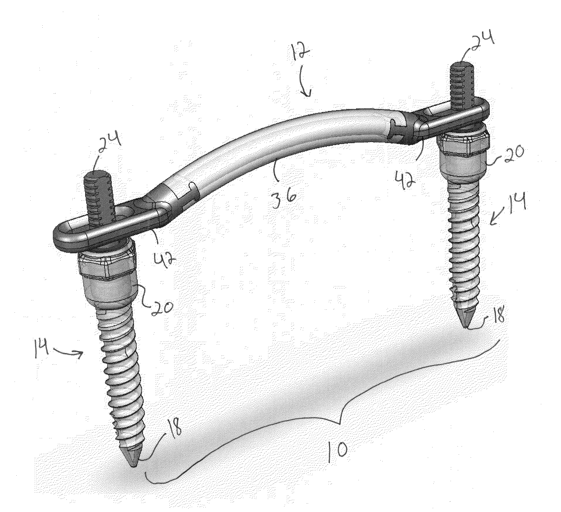
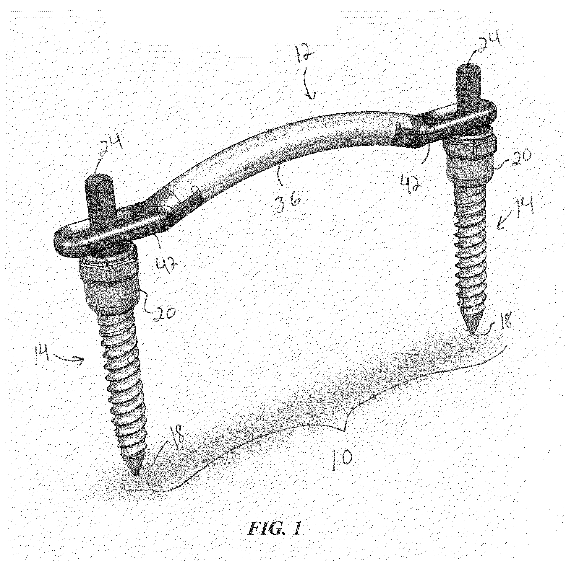
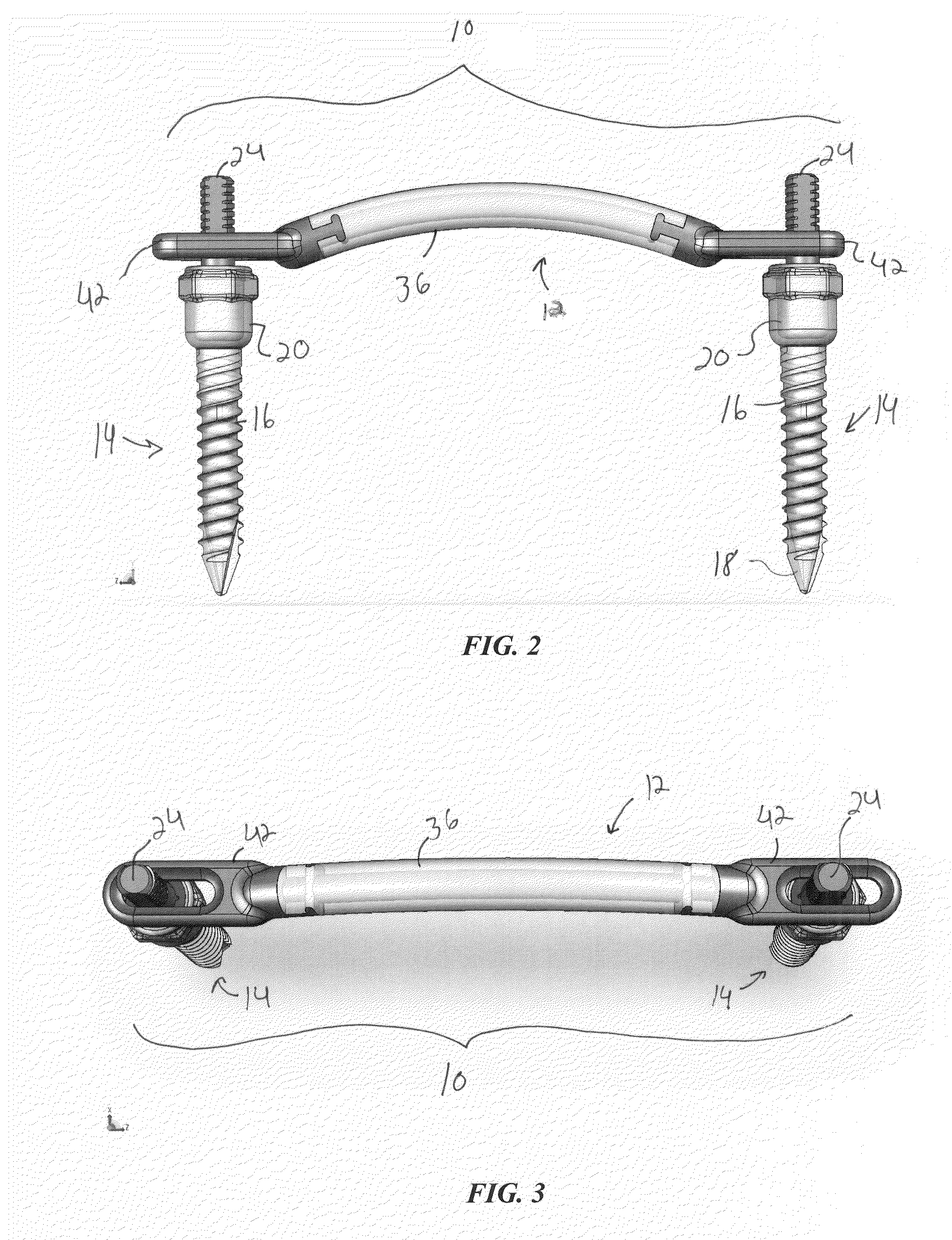
[0023]The present disclosure advantageously provides a spinal stabilization system and methods of use and manufacturing thereof that facilitate motion preservation of a spinal segment, provide a high degree of resistance to fatigue and cyclic loading associated with spinal segment forces, and promote bone growth without adding to the complexity of an implantation procedure. Referring now to the drawing figures in which like reference designations refer to like elements, an embodiment of a spinal stabilization system constructed in accordance with principles of the present invention is shown in FIGS. 1-5 and generally designated as “10.” The system 10 generally includes a spinal implant or prosthesis 12 engageable with one or more orthopedic anchors or screws 14. The spinal prosthesis may provide a desired degree of fusion, motion preservation, articulation, or the like depending on the particular application and patient's needs.

[0024]The one or more orthopedic anchors 14 may general...


PUM

PropertyMeasurementUnit
Lengthaaaaaaaaaa
Lengthaaaaaaaaaa
Fractionaaaaaaaaaa

Abstract

A spinal stabilization system, including a spinal implant having an elongate polymer body; a wire embedded in the body, the wire straining the polymer body; and a mounting element coupled to the elongate polymer body to facilitate engagement of the body to a spinal segment; and an orthopedic anchor having a threaded shaft; a head coupled to the threaded shaft, the head defining a cavity therein; a prosthesis coupling element at least partially disposed in the cavity and movable with respect to the head; and at least one asymmetrical ring circumscribing a portion of the prosthesis coupling element.

Description

CROSS-REFERENCE TO RELATED APPLICATION[0001]This application is related to and claims priority to U.S. Provisional Patent Application Ser. No. 61 / 234,600, filed Apr. 15, 2010, entitled “Spinal Fixation and Pedicle Screws,” the entirety of which is incorporated herein by reference.STATEMENT REGARDING FEDERALLY SPONSORED RESEARCH OR DEVELOPMENT[0002]n / aFIELD OF THE INVENTION[0003]The present invention relates to systems and methods of use thereof for orthopedic stabilization, and particularly, spinal stabilization.BACKGROUND OF THE INVENTION[0004]Spinal fusion is considered the “gold standard” for surgically treating patients whose condition has become so severe and debilitated that conservative, non-surgical measures fail to provide relief. Using bone grafts along with implants such as metal plates, rods and screws, spinal fusion adjoins two adjacent vertebrae, thus stabilizing the segment and easing the patient's pain, numbness, weakness and / or lack of mobility. Recently, advances i...

Claims


Application Information

Patent Timeline
IPC IPC(8): A61B17/70B29C47/02B29C45/14B29C48/06B29C48/154
CPCA61B17/7007A61B17/701A61B17/7011B29C45/14221B29C45/14262B29C45/14565B29L2031/7532B29C47/0035B29C47/025B29C2045/14245B29K2071/00B29K2705/00B29C47/0016B29C48/06B29C48/131B29C48/154
Inventor HAY, J. SCOTTSINGH, RYANJONES, DAVID BRADLEYFERRARI, NATHANAEL ROBERT
Owner HAY J SCOTT
Features
  • Generate Ideas
  • Intellectual Property
  • Life Sciences
  • Materials
  • Tech Scout
  • Unparalleled Data Quality
  • Higher Quality Content
  • 60% Fewer Hallucinations
Learn More