

Golf ball trajectory simulation method
a golf ball and trajectory simulation technology, applied in cad techniques, instruments, analogue processes for specific applications, etc., can solve the problems of complex air flow turbulence during flight, time-consuming and expensive, air flow turbulence around the body, etc., and achieve the effect of efficient development of golf balls
Inactive Publication Date: 2011-10-20
BRIDGESTONE SPORTS
View PDF13 Cites 17 Cited by
- Summary
- Abstract
- Description
- Claims
- Application Information
AI Technical Summary
Benefits of technology
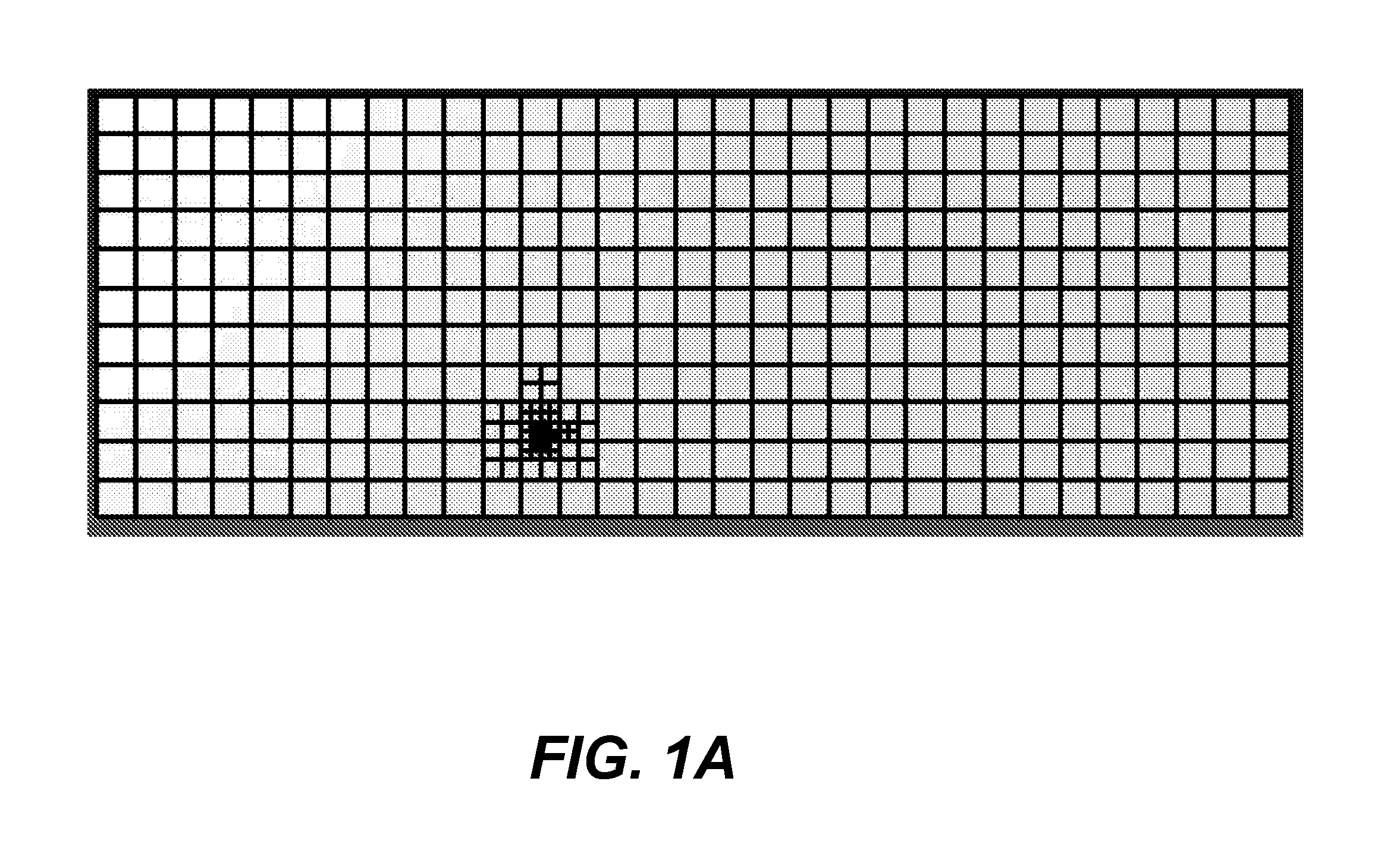
The present invention provides a method for efficiently developing golf balls by evaluating the trajectory of a golf ball having a plurality of dimples on a surface thereof without relying on actual physical prototypes. The method involves generating a grid within a virtual airflow space where the ball is to be launched, setting up a spherical golf ball model with dimples, dividing the grid into cells, setting a weight for the ball model, applying initial conditions to the ball model, initiating movement of the ball model, regenerating in an area of movement the grid near the ball model, and restoring the grid after the ball has passed through it. The method calculates the lift and drag coefficients for the ball in flight within the virtual airflow space, and calculates the flight distance and left-to-right dispersion for the ball. The method is adaptable to different ball models and can be used to develop new golf balls with improved trajectories.
Problems solved by technology
It is known that when a physical body such as a golf ball flies through the air, air flow turbulence arises around the body.
If the surface of the body has a complex shape or the body spins while flying, the air flow turbulence during flight becomes complex and exerts a major influence on the flight performance of the body, such as the flight distance.
However, such experimental evaluation based on actual physical prototypes, in addition to being time-consuming and expensive, is incapable of clearly establishing the causal relationships between the shapes and arrangement of the dimples and the aerodynamic properties of the ball.
For this reason, golf balls which have been newly designed based on evaluation results obtained by experimentation often fail to exhibit the intended performance.
Because such a process entails further expenditures of time and cost, golf balls cannot be efficiently developed in this way.
Method used
View moreImage
Smart ImageViewing Examples

Examples
examples
[0112]Examples of the invention and Comparative Examples are given below by way of illustration, and not by way of limitation.
Login to View More PUM
 Abstract
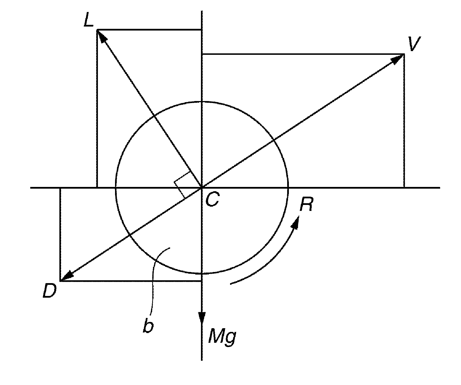
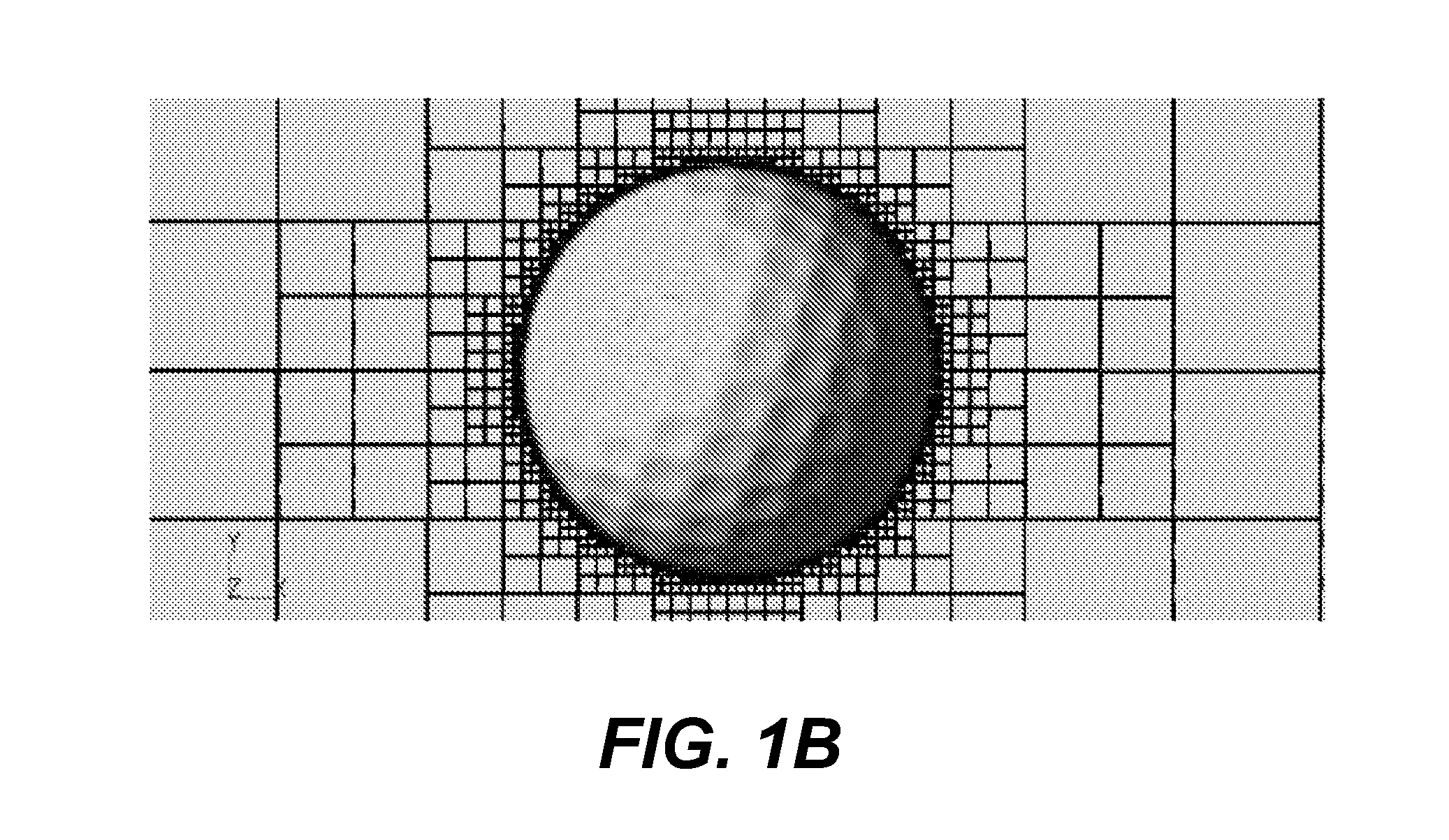
The invention is directed at a golf ball trajectory simulation method which sets up a golf ball model within a virtual airflow space where a grid has been generated, sets a weight for the ball model and applies initial conditions (initial velocity, launch angle, spin rate) to the ball model so as to cause the model to fly within the virtual airflow space, then calculates the lift coefficient and the drag coefficient for the golf ball from the air stream velocity, direction and pressure calculated in each grid cell, and calculates the flight distance and left-to-right dispersion for the golf ball from launch until landing by calculating the change in height, change in lateral direction, change in velocity and change in spin rate for the golf ball during flight. The trajectory simulation method divides the flight path of the golf ball model into two or three regions based on the criteria that Re=250,000 to 170,000 is a high-velocity region, Re=170,000 to 100,000 is a medium-velocity region and Re=100,000 and below is a low-velocity region, and sets up a height for the grid adjacent to the golf ball model surface in the high-velocity region (grid height A), a height for the grid adjacent to the golf ball model surface in the medium-velocity region (grid height B) and a height for the grid adjacent to the golf ball model surface in the low-velocity region (grid height B) such that grid height A<grid height B<grid height C.
Description
CROSS-REFERENCE TO RELATED APPLICATION[0001]This application is a continuation-in-part of copending application Ser. No. 12 / 763,425 filed on Apr. 20, 2010, the entire contents of which are hereby incorporated by reference.BACKGROUND OF THE INVENTION[0002]The present invention relates to a golf ball trajectory simulation method which estimates the trajectory of a golf ball having a plurality of dimples on the surface thereof by setting up a golf ball model on a computer and employing arithmetic operations by the computer to calculate elements of motion for the golf ball model.[0003]It is known that when a physical body such as a golf ball flies through the air, air flow turbulence arises around the body. If the surface of the body has a complex shape or the body spins while flying, the air flow turbulence during flight becomes complex and exerts a major influence on the flight performance of the body, such as the flight distance.[0004]Golf balls are most often provided with a large n...
Claims
Login to View More Application Information
Patent Timeline
 Patent Type & AuthorityApplications(United States)
IPC IPC(8): G06F17/10G06G7/57
CPCA63B45/00A63B69/36G06F2217/16G06F17/5018A63B2243/0029G06T13/20A63B2102/32G06F2111/10G06F30/23G06F30/20G06F30/28A63B69/3691
InventorSATO, KATSUNORI
OwnerBRIDGESTONE SPORTS