Duct Sound Damper For A Flow Machine

a flow machine and duct sound technology, applied in the direction of heat measurement, instruments, manufacturing tools, etc., can solve the problems of unwanted acoustic radiation, fiber loss, and limited flow rate,

Active Publication Date: 2011-10-27
MAN ENERGY SOLUTIONS SA
View PDF9 Cites 3 Cited by
  • Summary
  • Abstract
  • Description
  • Claims
  • Application Information

AI Technical Summary

Benefits of technology

[0006]It is an object of the present invention to provide an improved duct sound damper for a flow machine, particularly for a compressor, and further to provide a me...

Problems solved by technology

During the operation of flow machines, there often occur vibrations that are marked, for example, by pressure fluctuations in the fluid, periodic excitations in the machine, or the like, and which result in unwanted acoustic radiation.
These da...

Method used


Image

  • Duct Sound Damper For A Flow Machine
  • Duct Sound Damper For A Flow Machine
  • Duct Sound Damper For A Flow Machine

Examples


Embodiment Construction

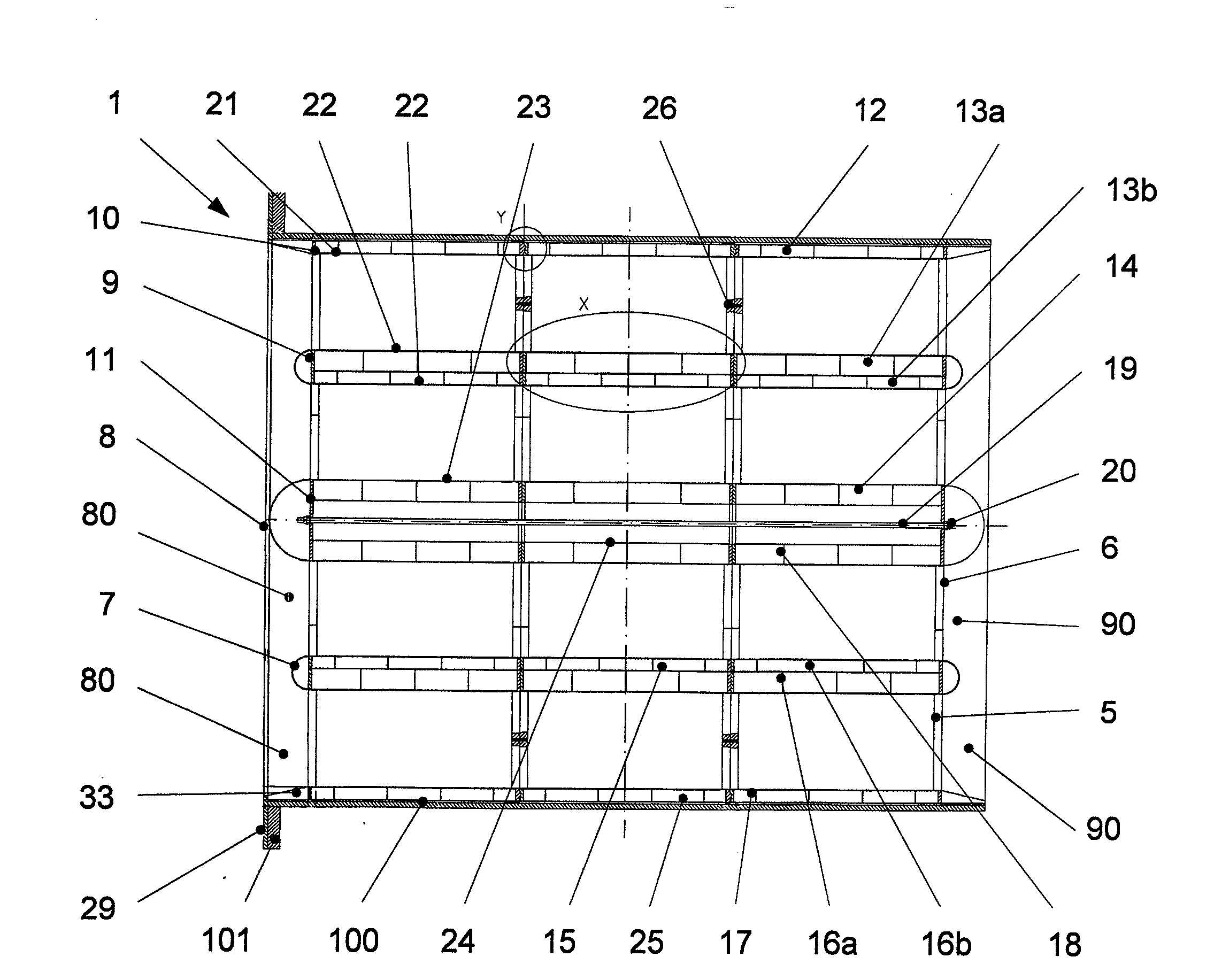
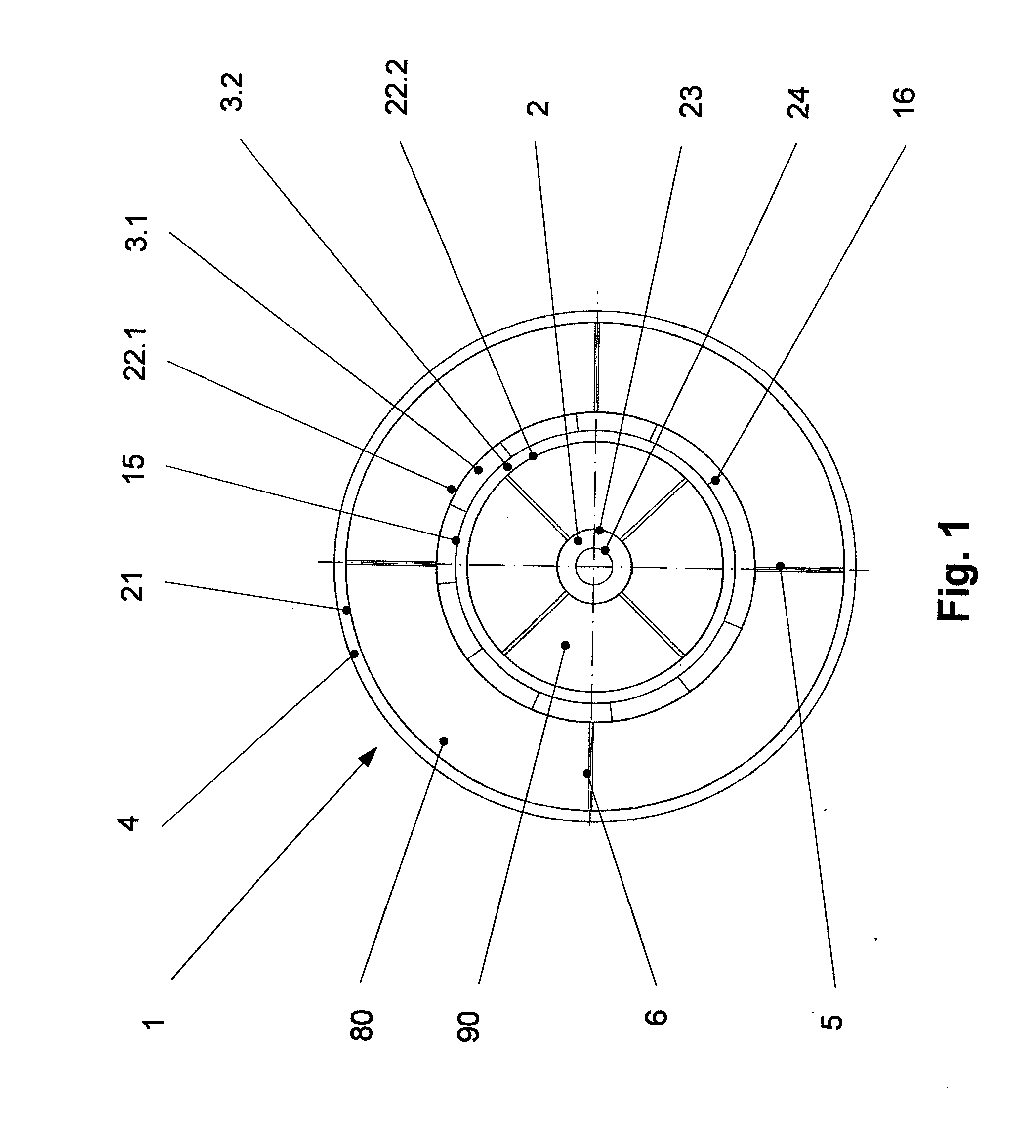
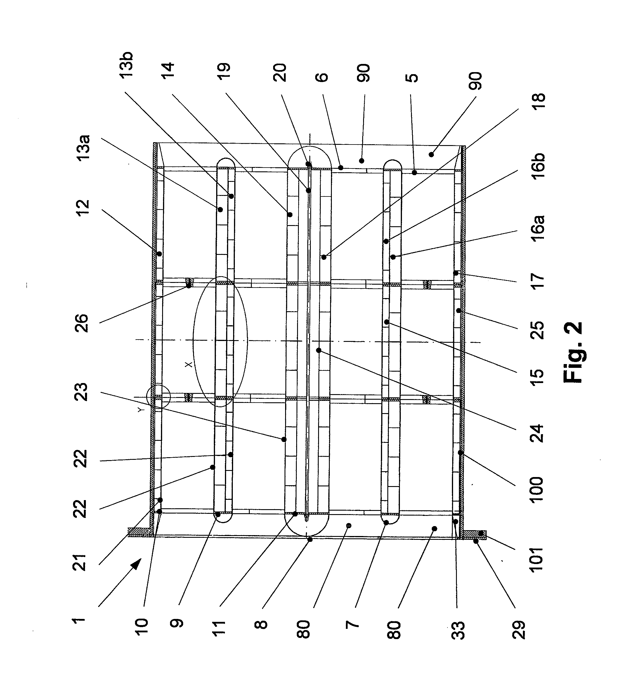
[0034]A duct sound damper according to an embodiment example of the present invention will be described with reference to the accompanying drawings.

[0035]FIGS. 1 to 6 show the duct sound damper (1) in its entirety and associated elements for constructing the damper members (2; 3; 4). The duct sound damper (1) is inserted into a flow duct, designated by reference numeral 100, and detachably connected thereto by flanges (101).

[0036]In the embodiment example of the present invention, the duct sound damper (1) comprises three main elements. These main elements are detachably connected to one another along the length by pins (21) and a central tie rod (19). (FIG. 2).

[0037]As regards their basic construction, all of the duct sound damper elements are identical and are adapted to the particular installation situation only when assembled.

[0038]A duct sound damper element substantially comprises a central damper member, inner damper member, and outer damper member (2; 3; 4), each of which is...


PUM

PropertyMeasurementUnit
Forceaaaaaaaaaa
Circumferenceaaaaaaaaaa
aaaaaaaaaa

Abstract

Duct sound damper for deliberate reduction of sound waves for a flow machine, particularly for a compressor, with a housing having at least one horizontally extending acoustically reflective back wall and at least one front cover plate. At least one flow channel connected together through inlet opening and outlet opening is enclosed by at least one damper member reducing the sound. The damper member includes horizontal axial stringers, circumferential stringers, the front cover plate, at least one sound-insulating metal element extending horizontal to the flow-guiding cross section, and the acoustically reflective back wall.

Description

BACKGROUND OF THE INVENTION[0001]1. Field of the Invention[0002]The invention is directed to a duct sound damper for a flow machine, particularly for a compressor.[0003]2. Description of the Related Art[0004]During the operation of flow machines, there often occur vibrations that are marked, for example, by pressure fluctuations in the fluid, periodic excitations in the machine, or the like, and which result in unwanted acoustic radiation. It is known for purposes of reducing acoustic transmission and emission to arrange duct sound dampers, or inline silencers, upstream and / or downstream of flow machines or stages thereof. The fluid flows through these duct sound dampers to reduce sound propagation.[0005]A duct sound damper is known in which fluid circulates around damper members or splitters received in a housing. These damper members are often made of porous fiber material, for example, glass wool, or the like, and there is a risk of fiber loss so that only limited flow rates are ...

Claims


Application Information

Patent Timeline
IPC IPC(8): E04B1/82B23P17/00
CPCY10T29/49826F16L55/0331
Inventor BUSSOW, RICHARD
Owner MAN ENERGY SOLUTIONS SA
Why Eureka
Try Eureka