Packing bag with radio frequency identification function and manufacturing method thereof

a technology of radio frequency identification and packaging bags, which is applied in the direction of manufacturing tools, paper/cardboard containers, instruments, etc., can solve the problems of requiring a higher difficulty level for duplication, electromagnetic signals will be damaged, and cannot be transmitted to the reader, and readers will be unable to read the information from the rfid tag

Active Publication Date: 2011-10-27
TAIWAN LAMINATION INDS
View PDF6 Cites 19 Cited by
  • Summary
  • Abstract
  • Description
  • Claims
  • Application Information

AI Technical Summary

Benefits of technology

[0025]A further objective of the present invention is to provide a packaging bag further comprising a protective sticker covered onto the two conductive films to protect the RFID chip and the two conductive films and prevent the components from being damaged or falling apart due to collisions.

Problems solved by technology

The RFID tag described in the present invention primarily refers to the active RFID tag, and this type of RFID tag is the mainstream product of the present RFID tag market, and has the following advantages:
(1) It provides a greater capacity for storing information;
(2) It provides a longer communication distance;
(3) It requires a higher level of difficulty for duplication;
(4) It has a larger tolerance to environmental changes; and
(5) A reader can read several RFID tags simultaneously.
The image pulse has a phase opposite to the phase of the electromagnetic signal transmitted from the transceiver antenna 11, and the image pulse and the electromagnetic signal have an offset interference, so that the electromagnetic signal will be damaged and cannot be transmitted to the reader, and the reader will be unable to read the information from the RFID tag 10 properly.
However, the aforementioned RFID tag 10 cannot be applied to metal bags due to the image pulse problem.
If a user attaches the RFID tag 10 onto a metal bag, the transmission distance of the RFID tag 10 may probably drop to zero, and the reader will be unable to read the RFID tag 10, and the user will be unable to manage each delivering item accurately.

Method used


Image

  • Packing bag with radio frequency identification function and manufacturing method thereof
  • Packing bag with radio frequency identification function and manufacturing method thereof
  • Packing bag with radio frequency identification function and manufacturing method thereof

Examples


Embodiment Construction

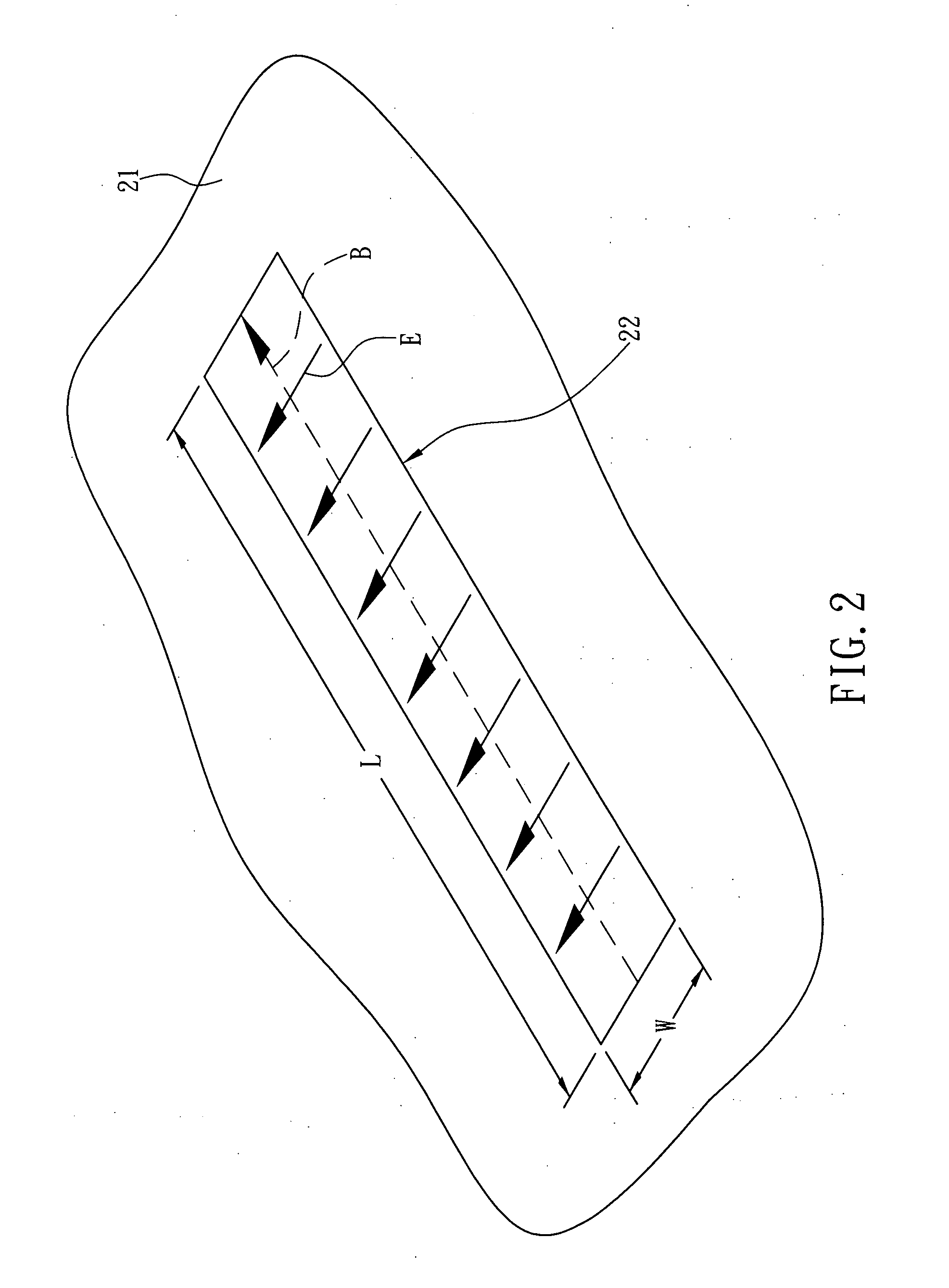
[0037]The present invention mainly adopts the principle of a slot antenna, and uses a metal layer inside a packing bag as an antenna of a RFID chip. With reference to FIG. 2 for the principle of the slot antenna, a slot 22 is formed on an infinitive flat conductor plate 21, and the slot 22 has a length L and a width W, and the length L is much greater than the width W. If a voltage difference is applied on both sides having a longer length, then an electric field E and a magnetic field B will be produced as shown in FIG. 2, such that the slot antenna can have the function of receiving and transmitting electromagnetic signals.

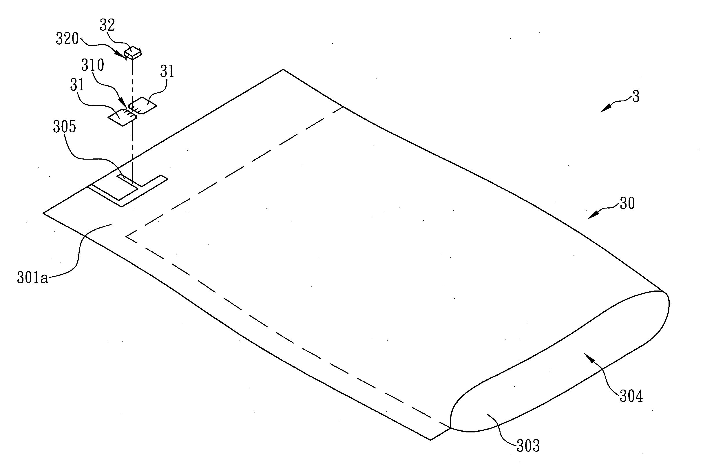
[0038]The present invention uses the characteristics of the aforementioned slot antenna to change the structure of a general packing bag to design a packing bag with a RFID function. In a preferred embodiment of the present invention as shown inFIG. 3, the packing bag 3 comprises a bag body 30, two conductive films 31 and a RFID chip 32, wherein the RFID chip 32...


PUM

PropertyMeasurementUnit
conductiveaaaaaaaaaa
sizeaaaaaaaaaa
data transmission rateaaaaaaaaaa

Abstract

The present invention is to provide a packing bag with a RFID function, which comprises a bag body, two conductive films and a RFID chip. The metal layer includes a first slot formed at a position proximate to an edge of the bag body and is used as a slot antenna. A second slot is formed between the two conductive films, and has a size capable for fixing the pins on two corresponding sides of the RFID chip onto the two conductive films respectively. The two conductive films are fixed on an external surface of an insulating layer of the bag body at a position corresponding to the first slot, such that the two conductive films can be coupled to two feed-in points of the slot antenna respectively, and the RFID chip can receive and transmit electromagnetic signals through the slot antenna (or the metal layer) accordingly.

Description

FIELD OF THE INVENTION[0001]The present invention relates to a packing bag with a RFID function, which comprises a metal layer, two conductive films and a RFID chip. The metal layer has a first slot formed at a position proximate to an edge of the packing bag and is used as a slot antenna. The two conductive films are used for increasing the coupling area of the pins on the two corresponding sides of the RFID chip, and are fixed on an external surface of an insulating layer of the packing bag at a position corresponding to the first slot, such that the two conductive films can be coupled to two feed-in points of the slot antenna respectively, and the RFID chip can receive and transmit electromagnetic signals through the slot antenna (or the metal layer) accordingly.BACKGROUND OF THE INVENTION[0002]Radio frequency identification (RFID) technology also known as radio frequency identification tag (RFID tag) is a communication technology for identifying a specific object through an elec...

Claims


Application Information

Patent Timeline
Patent Type & Authority Applications(United States)
IPC IPC(8): B65D90/00B23P19/00
CPCB31B2219/90B31B2219/9006B31B2221/10Y10T29/49826B65D33/004B65D2203/10B65D31/02B31B2160/10B31B70/81B31B2150/00B31B70/8122B31B2170/20
Inventor CHEN, YUNG-SHUN
Owner TAIWAN LAMINATION INDS
Why Eureka
Try Eureka