
Method for Tracing Individual Dies

a die and die traceability technology, applied in the field of die marking and die traceability of dies, can solve the problems of inability to easily identify or see individual dies

Inactive Publication Date: 2011-10-27
MEDTRONIC INC
View PDF2 Cites 8 Cited by
  • Summary
  • Abstract
  • Description
  • Claims
  • Application Information

AI Technical Summary

Problems solved by technology

Although the encapsulant protects the dies or stack of dies, the individual dies are not visible or easily identifiable.

Method used


Image

  • Method for Tracing Individual Dies
  • Method for Tracing Individual Dies
  • Method for Tracing Individual Dies

Examples


Embodiment Construction

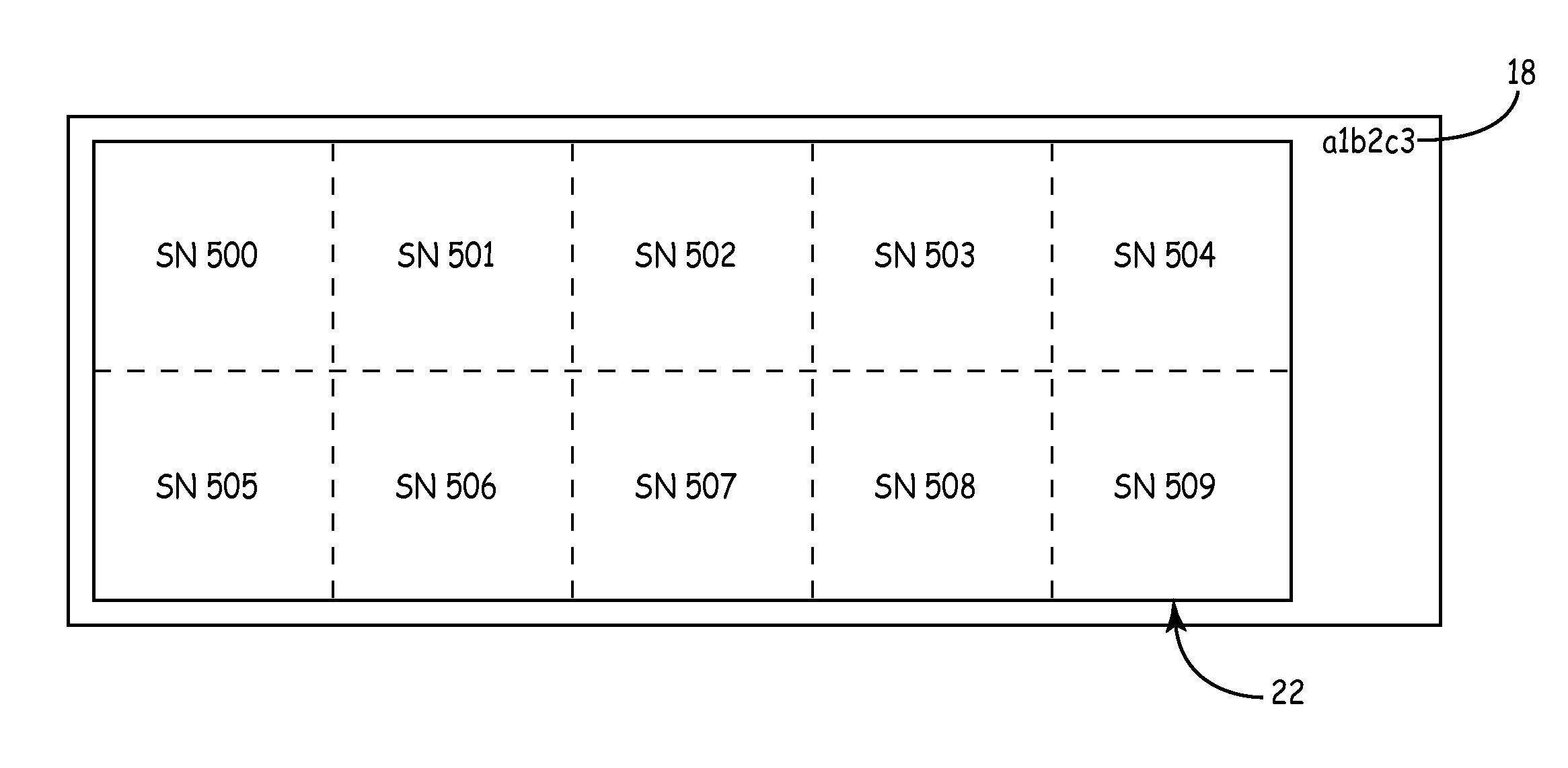
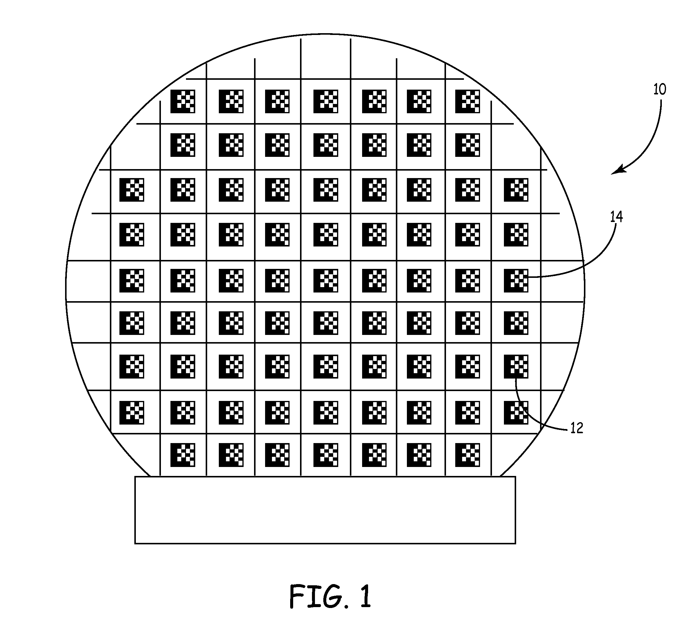
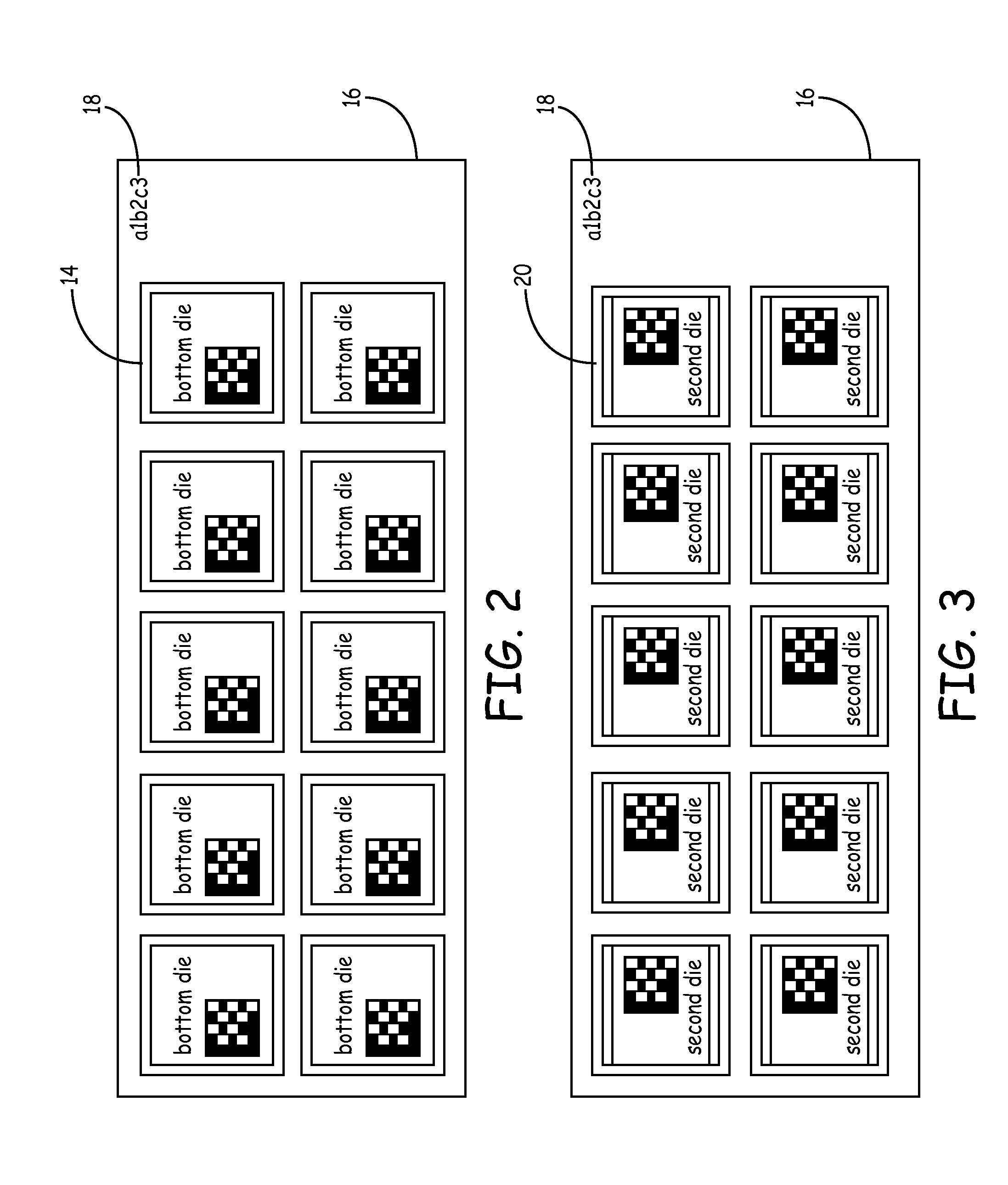
FIG. 1 depicts a wafer 10 having a plurality of die 12 formed on a wafer surface. Typically, the wafer has been thinned in order to produce thin die. In this embodiment, each of the die is uniquely marked with a data matrix 14. The data matrix 14 contains readable information about the die. For example, the data matrix on each of the die can contain the wafer lot number, the wafer number, the x-y location of the die on the wafer, and combinations of any or all of the listed information. The wafer number and / or wafer lot number can be associated with information such as date of manufacture, location of manufacture, identification of equipment used during manufacture, source of raw material, raw material analysis results, and combinations of any of them. Of course, the marking on the die could be of any other type including barcode, and alpha-numeric symbols, or a combination of any of them. The markings may be made using marking methods such as digital lithography, printing using opa...


PUM


Abstract

A method for tracing individual dies within stacked chip scale packages includes the steps of recording unique die identifiers from layers of marked dies and associating the unique identifiers with a die bonding substrate and the resulting die or stacked chip scale packages. The unique die identifiers are also associated with wafer numbers, x-y positions on a wafer, wafer lot numbers or any combination thereof.

Description

BACKGROUNDThe invention relates generally to die marking and die traceability of dies in chip scale packages (CSPs) and stacked chip scale packages (SCSPs).Many manufacturers are using stacked chip scale packages (SCSPs) that contain multiple thinned die stacked on top of one another. Such a configuration is desirable because it saves space on a circuit board. Saving space on a circuit board becomes more important as components and the devices that use such components become smaller in area and volume. Single dies and SCSPs are also used in system in packages (SIPs)Typically these SCSPs and SIPs are encapsulated for protection and heat dissipation. Although the encapsulant protects the dies or stack of dies, the individual dies are not visible or easily identifiable. However, in the event of a quality or reliability issue associated with the SCSP or SIP within a device, it would be desirable to be able to trace the origin of the die stack to an individual wafer.SUMMARYIn one embodim...

Claims


Application Information

Patent Timeline
Patent Type & Authority Applications(United States)
IPC IPC(8): G06F17/00H01L21/50G06K19/06H01L21/78
CPCH01L23/544H01L2223/54406H01L2223/54413H01L2223/54433H01L2223/54473H01L2924/0002H01L2223/5448H01L2223/54486H01L2924/00
Inventor MEYERSON, CHARLES M.DICKES, ERIC J.GORTON, WILLIAM V.GRAHAM, STEPHEN W.HEAMES, KENNETHJOHNSON, DENNIS B.OHME, CHRISTOPHER D.WARREN, STEVEN C.
Owner MEDTRONIC INC
Learn More