

Configuration of a rear fuselage tail cone of an aircraft with an auxiliary power unit
- Summary
- Abstract
- Description
- Claims
- Application Information
AI Technical Summary
Benefits of technology
Problems solved by technology
Method used
Image

Examples
Embodiment Construction
[0024]The present invention is designed to overcome the drawbacks of above-mentioned traditional APU positioning.
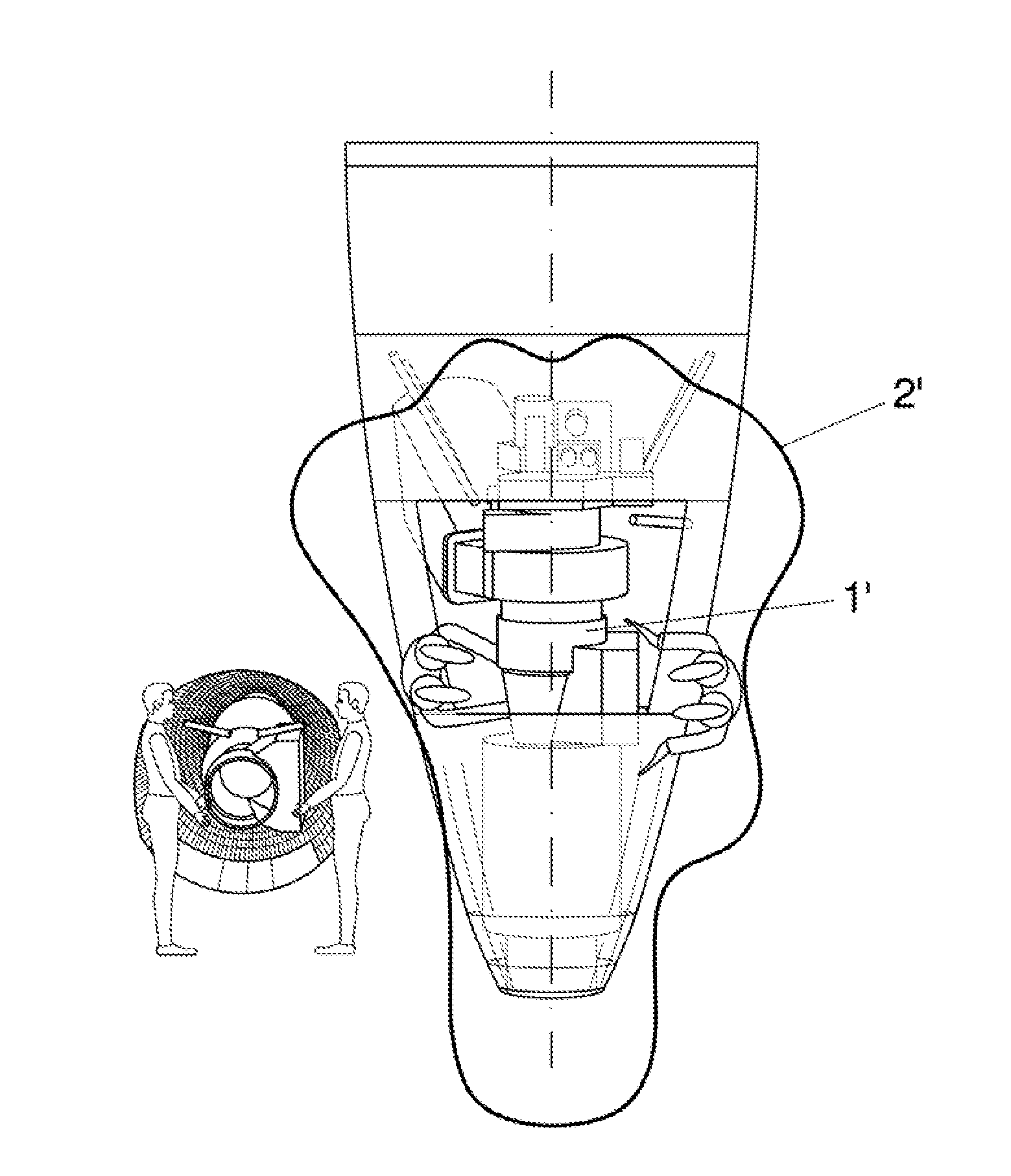
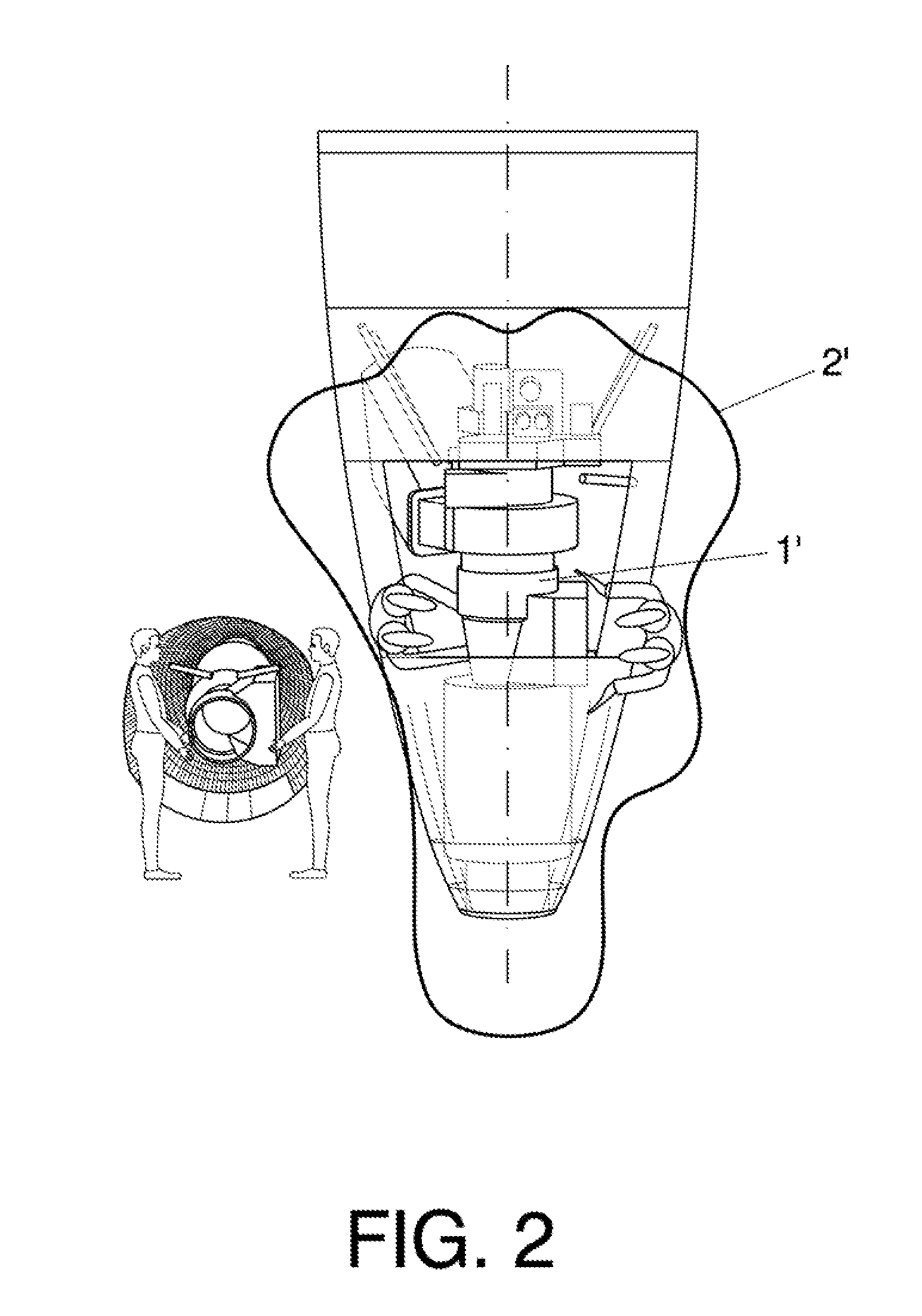
[0025]The present invention intends to serve for the purpose of improving the relationship between the aerodynamic requirements of the tail cone with the constantly increasing size of the APU as explained above. Thus, the present invention proposes a new configuration for the rear fuselage tail cone of an aircraft with an auxiliary power unit in which a fire compartment of the rear fuselage tail cone constitutes housing for the auxiliary power unit. The auxiliary power unit being housed laterally and asymmetrically with respect to a longitudinal axis (X) of the rear fuselage tail cone and the auxiliary power unit being directly fasten attached to a structural skin wall of the fire compartment.
[0026]This new disposition, asymmetrical with respect to the longitudinal axis of the aircraft, provides single side access to the APU located inside the fire compartment of the tail...
PUM
| Property | Measurement | Unit |
|---|---|---|
| Elastomeric | aaaaa | aaaaa |
| Length | aaaaa | aaaaa |
Abstract
Description
Claims
Application Information