Power operated chuck

Active Publication Date: 2011-10-27
SMW AUTOBLOK SPANNSYST GMBH
View PDF6 Cites 18 Cited by
  • Summary
  • Abstract
  • Description
  • Claims
  • Application Information

AI Technical Summary

Benefits of technology

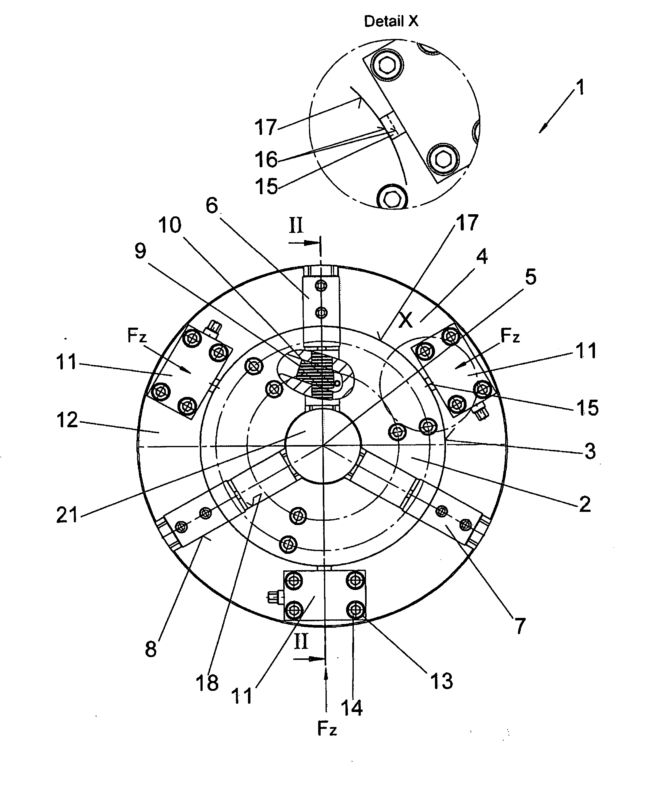
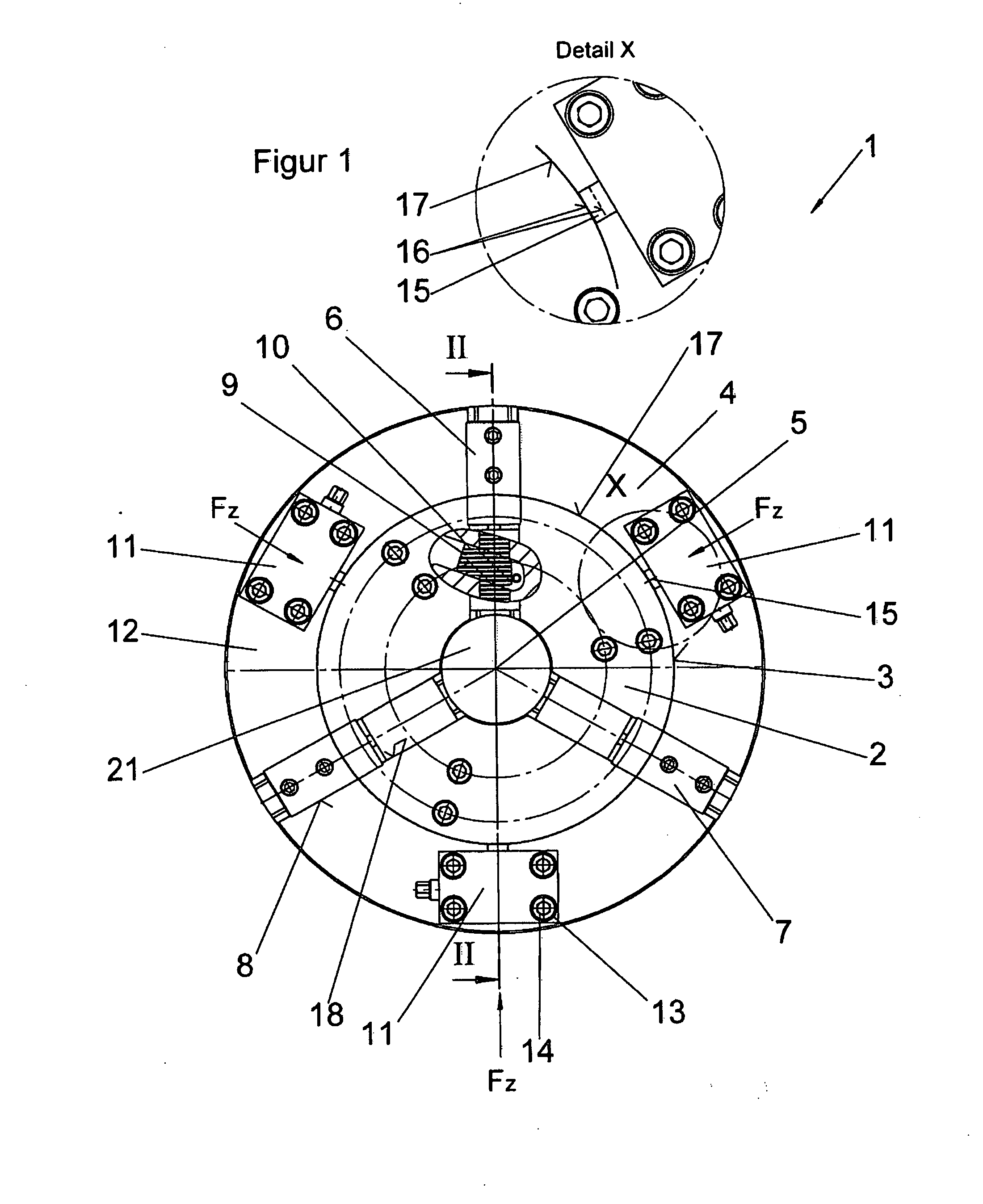
At least one centering device is provided on a side which applies a centering force radially onto the workpiece, and therefore the workpiece can be centered exactly once it has been centered in three clamping jaws, because the corresponding centering device means that the longitudinal axis of the workpiece can be positioned flush in relation to the longitudinal axis of the chuck without the centering force acting on the clamping jaws. This is because the clamping jaws are connected in a force-locking arrangement with an actuating device, in particular with a piston, via a wedge rod. However, the 
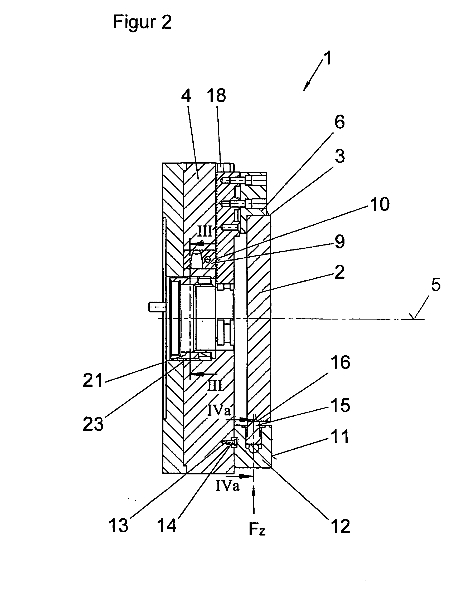
piston is mounted in a base body of the chuck with a play that is a feature of the manufacturing process, and so this play can be compensated for by means of the corresponding centering device. As a result, the centering force of the corresponding centering device does not act on the clamping jaws and therefore on the wedge rod, the actuating device and the chuck, but rather compensates for the existing bearing play and / or error tolerances, which are in the region of about 5 μm, in particular with extremely large outside diameters. These are significant error tolerances for precision components and can therefore be compensated for by the centring devices in such a way that the workpieces in the chuck can be installed precisely centrally in the chuck.
During the machining process, half of the existing material and therefore half of the inherent weight is sometimes removed from the workpiece by cutting processes; therefore the inherent weight of the workpiece is reduced during the machining process, with the effect that the geometrical clamping conditions are also influenced. The centering devices can be moved independently from the clamping jaws, therefore such changes in the clamping conditions can be compensated for by the centring devices during the machining process, with the effect that the clamped workpiece can be positioned precisely centrally in relation to the chuck at all times without any variation in the clamping force exerted by the clamping jaws.
Furthermore, the centering device acts on the surface of the clamped workpiece, with the effect that the workpiece is supported not only by the clamping jaws but also by the centring devices on the base body of the chuck.
It is particularly advantageous if three clamping jaws are arranged offset at an angle of 120° in relation to one another, and if one of the centering devices is arranged in between two adjacent clamping jaws. This construction results in the situation that six clamping jaws and centering devices converging on one another at an angle of 60° act on the workpiece, with the effect that the workpiece is reliably supported on the chuck not only by the clamping jaws but also by the centering devices.
Furthermore, the centering devices can be actuated synchronously, jointly, or independently from one another, with the effect that precise alignment of the workpiece is achieved by the one or more centering devices, depending on the clamping situation.
These setting possibilities mean that the position of the workpiece can be realigned with regard to the material reduction and therefore that the centering devices permit the realignment in position due to the change in position of the workpiece in relation to the midpoint of the chuck caused by the change in weight. As a result, the workpiece is positioned exactly centrally in relation to the chuck throughout the entire machining process; there is no need to remove and reclamp the workpiece because the workpiece is permanently held by the clamping jaws of the chuck throughout the machining processes. It is only the centering devices that need to be actuated in order to reposition the workpiece exactly centrally.

Problems solved by technology

This is to say, that if it is necessary to secure workpieces reliably that have a large inherent weight and an exterior diameter of more than 0.5 metres then chucks of the prior art cannot be used, because workpieces of this kind cannot be centered exactly.
Error tolerances of this kind cannot be excluded for reasons of manufacturing requirements.
Therefore, there is an inaccuracy between the position of the workpiece and the centre of the chuck.
It is not possible to compensate for these existing inaccuracies in the subsequent machining of the workpieces, with the effect that there are error tolerances in the final status of the machined workpiece, although these should be avoided in high-precision components.
It has proved to be a further disadvantage in the disclosed chucks that clamping errors arise during the machining process which is often time consuming and complicated, because the machined workpiece becomes lighter during the machining process as a result of having material removed from it.

Method used


Image

  • Power operated chuck
  • Power operated chuck
  • Power operated chuck

Examples


Embodiment Construction

FIGS. 1, 2 and 3 show a chuck 1, by means of which a rotationally symmetrical, preferably round, workpiece 2 is held from the outside on a machine tool (not shown) for the purpose of machining the workpiece 2 by metal cutting. The chuck 1 consists of a base body 4, the longitudinal axis of which is identified by the reference number 5. Three clamping jaws 6, 7 and 8 are mounted in a radially movable arrangement in guide grooves 18 aligned with the longitudinal axis 5. The clamping jaws 6, 7 and 8 are each driven by a wedge rod 9 that is arranged movably in the base body 4 in a usual manner. Gearing 10 is provided between the each of the wedge rods 9 and the clamping jaws 6, 7 or 8, with the effect that a force-locking active connection is provided between each of the clamping jaws 6, 7 or 8 and the corresponding wedge rod 9. Each of the wedge rods 9, as can be seen in particular in FIG. 3, can be driven by an actuating element 21. The actuating element 21 is normally configured as a...


PUM

PropertyMeasurementUnit
Forceaaaaaaaaaa
Radiusaaaaaaaaaa

Abstract

A power-operated chuck (1, 1′) for machine tools a base body (4) attachable to the machine tool,at least two clamping jaws (6, 7, 8) held in a movable arrangement in the base body (4) and are synchronously controlled and moved radially onto the workpiece (2, 2′) to be clamped by means of one wedge rod (9) each, and with an actuating element (21) held in an axially movable arrangement in the base body (4) and connected in a force-locking arrangement with each of the wedge rods (9) and held coaxially in the base body (4) in relation to its longitudinal axis (5), there being play (23) between the actuating element (21) and the base body (4), the chuck (1, 1′) permitting central positioning of the workpiece (2, 2′) to be clamped in relation to the longitudinal axis (5) of the chuck (1, 1′) and, the chuck permitting the centering adjustment to be undertaken permanently throughout the machining process.

Description

BACKGROUND OF THE INVENTION1. Field of the InventionThe present invention relates to a power-operated chuck.2. Description of the Prior ArtPower-operated chucks of this kind are disclosed in EP 0069917 or EP 0085782. These power-operated chucks have been developed by the patent Assignee and have been successfully marketed by the same for decades. These power-operated chucks have proven effective in practice.EP 0085782, in particular, shows that each of the clamping jaws has a compensation clamping jaw set which is suitable for clamping unevenly shaped workpieces and can be advanced radially independently from the actual clamping jaw set. Both the clamping jaw set and the centering clamping jaws can be actuated by the wedge rods.The chucks developed and sold by the patent Assignee have one technical deficit. This is to say, that if it is necessary to secure workpieces reliably that have a large inherent weight and an exterior diameter of more than 0.5 metres then chucks of the prior ...

Claims


Application Information

Patent Timeline
IPC IPC(8): B23B31/16
CPCB23B31/16045B23B2270/12B23Q3/183Y10T279/1973Y10T279/19Y10T279/26Y10T279/10
Inventor HELM, PETER
Owner SMW AUTOBLOK SPANNSYST GMBH
Why Eureka
Try Eureka