
Handheld apparatus

a handheld apparatus and touch technology, applied in the direction of electronic switching, pulse technique, instruments, etc., can solve the problems of unnecessarily troubled users, touch panel may perform some operations incorrectly, and the capacitive touch sensing apparatus may be interfered, so as to prolong the working and standby time of the handheld apparatus and reduce power consumption

Inactive Publication Date: 2011-10-27
HTC CORP
View PDF3 Cites 10 Cited by
  • Summary
  • Abstract
  • Description
  • Claims
  • Application Information

AI Technical Summary

Benefits of technology

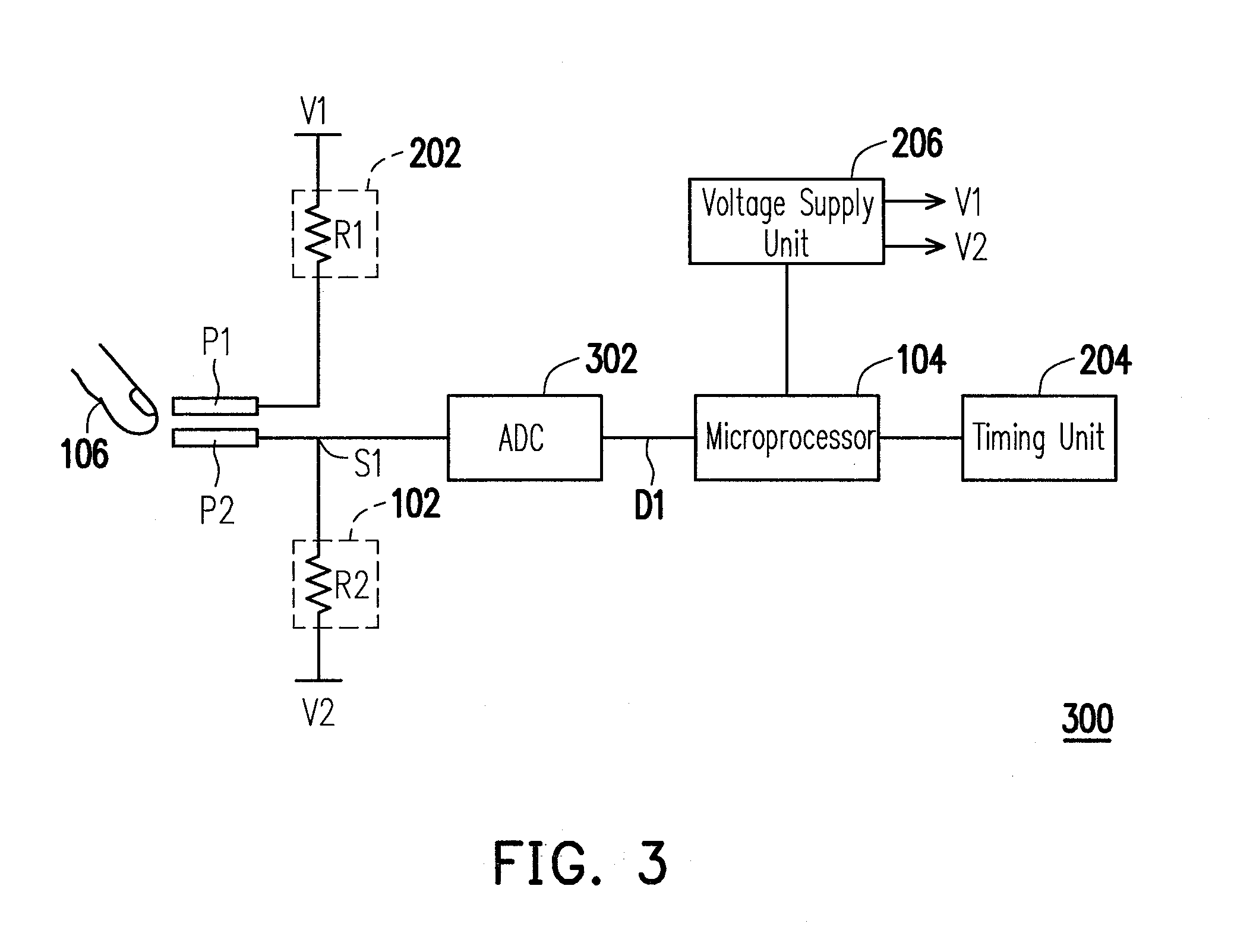
The present invention is about a handheld apparatus with a touch sensing apparatus that reduces power consumption and increases the working time of the handheld apparatus. This is achieved by using a first touch pad and a second touch pad, an impedance unit, and a microprocessor. When the input tool touches both touch pads simultaneously, a touch voltage signal is generated, which is then executed by the microprocessor. The handheld apparatus also includes a voltage supply unit, a timing unit, a current-limiting protection unit, an analog-to-digital converter, and a body with different surfaces for the touch pads. The technical effect of the invention is to reduce power consumption and increase the working time of the handheld apparatus.

Problems solved by technology

A capacitive touch sensing apparatus may be interfered by the sweat on the user's hand or electromagnetic waves.
As a result, the touch panel thereof may perform some operations incorrectly, such as mistakenly opening or closing some programs.
Obviously, such incorrect operations will trouble the user unnecessarily.
In addition, because the sensing capacitors have to be constantly charged, a lot of power is consumed and the standby and working time of the touch phone is shortened.

Method used


Image

  • Handheld apparatus
  • Handheld apparatus
  • Handheld apparatus

Examples


Embodiment Construction

[0031]Reference will now be made in detail to the present preferred embodiments of the invention, examples of which are illustrated in the accompanying drawings. Wherever possible, the same reference numbers are used in the drawings and the description to refer to the same or like parts.

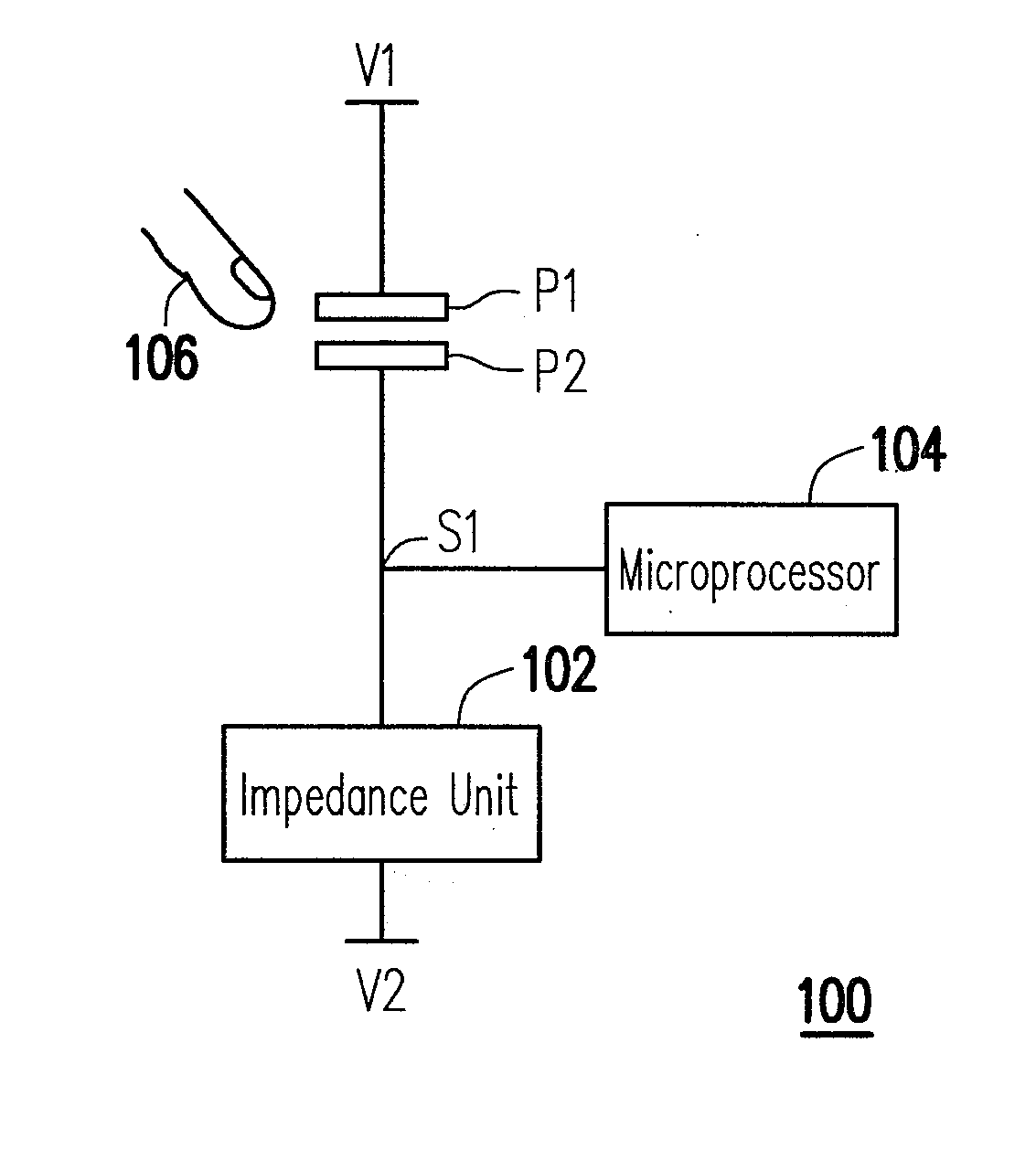
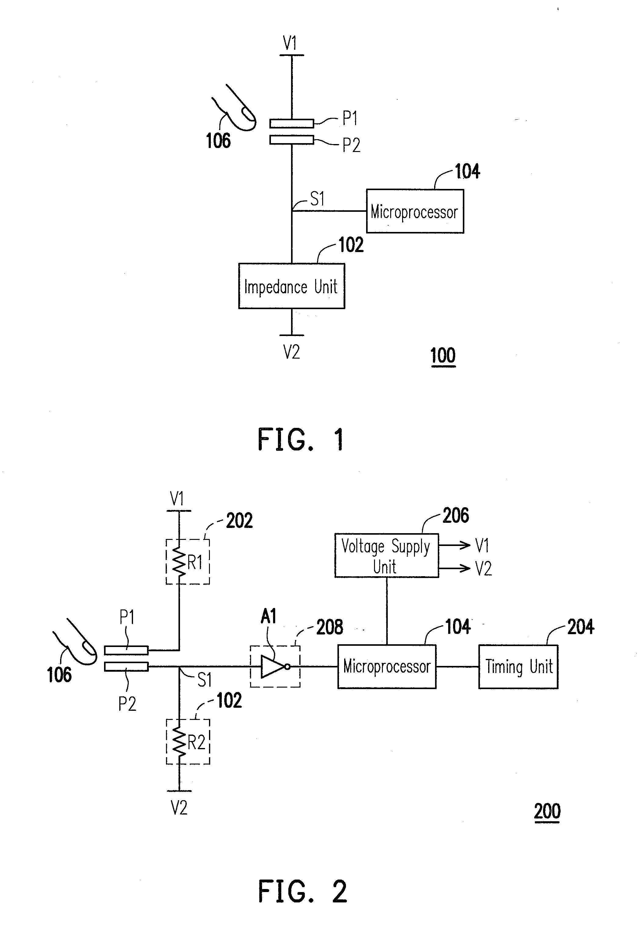
[0032]FIG. 1 is a block diagram of a touch sensing apparatus according to an embodiment of the present invention. Referring to FIG. 1, the touch sensing apparatus 100 includes a touch pad P1, a touch pad P2, an impedance unit 102, and a microprocessor 104. The touch pad P1 is coupled to a reference voltage V1. The impedance unit 102 is coupled between the touch pad P2 and a reference voltage V2. The microprocessor 104 is coupled to the touch pad P2.

[0033]When an input tool 106 (for example, a finger) having a resistance smaller than that of the impedance unit 102 touches the touch pad P1 and the touch pad P2 simultaneously, the touch pad P1 and the touch pad P2 are turned on, so that the voltage leve...


PUM


Abstract

A handheld apparatus is provided. The handheld apparatus includes a first touch pad, a second touch pad, an impedance unit, and a microprocessor. When an input tool touches the first touch pad and the second touch pad simultaneously, a touch voltage signal is generated on a common contact of the second touch pad and the impedance unit, wherein the resistance of the impedance unit is greater than that of the input tool. The microprocessor executes a specific function according to the touch voltage signal.

Description

CROSS-REFERENCE TO RELATED APPLICATION[0001]This application claims the priority benefit of Taiwan application serial No. 99113293, filed on Apr. 27, 2010. The entirety of the above-mentioned patent application is hereby incorporated by reference herein and made a part of this specification.BACKGROUND OF THE INVENTION[0002]1. Field of the Invention[0003]The present invention generally relates to a handheld apparatus, and more particularly, to a touch sensing apparatus of a handheld apparatus.[0004]2. Description of Related Art[0005]Along with the development of technologies, touch sensing apparatuses have been broadly used and brought a lot of convenience to our daily life. A user can execute various functions provided by a touch sensing apparatus by simply touching the touch sensing apparatus. Thus, the user's operation is made very simply.[0006]Taking touch phones as an example, capacitive touch sensing apparatus is one of the most common touch sensing apparatuses presently adopte...

Claims


Application Information

Patent Timeline
Patent Type & Authority Applications(United States)
IPC IPC(8): G06F3/045
CPCH03K17/9645
Inventor CHEN, MING-YUCHOU, FU-CHIANG
Owner HTC CORP
Learn More