Cooling apparatus and method

a technology of cooling apparatus and cooling method, which is applied in the direction of lighting and heating apparatus, fluid pressure control, instruments, etc., to achieve the effect of improving operation efficiency

Inactive Publication Date: 2011-11-03
LEANECO APS
View PDF20 Cites 48 Cited by
  • Summary
  • Abstract
  • Description
  • Claims
  • Application Information

AI Technical Summary

Benefits of technology

[0031]The invention incorporates redundancy in a modular architecture by cooling each heat source with a pa

Problems solved by technology

Problems, e.g. malfunction, may occur if the equipment overheats, so it

Method used


Image

  • Cooling apparatus and method
  • Cooling apparatus and method
  • Cooling apparatus and method

Examples


Embodiment Construction

Further Options and Preferences

[0040]The present invention may provide a flexible solution to the problem of cooling a data centre efficiently. The invention may utilize natural and non-water-based refrigerants. The invention may provide scalable apparatus, e.g. to enable tailored control of cooling system, e.g. in accordance with a business plan or proposed development. The scalability may also enable increases in the overall power density of a rack to be catered for, thus supporting the development of high power density blade servers and network equipment.

[0041]By providing heat exchangers associated with particular heat sources, the invention may limit or remove the need for forced airflow, which is standard in conventional cooling solutions. Similarly, the invention may remove the need for computational fluid dynamics (CFD) analysis of air flow patterns within a space to be cooled, and particularly the change of such patterns during operation, service and maintenance. This may b...


PUM


Abstract

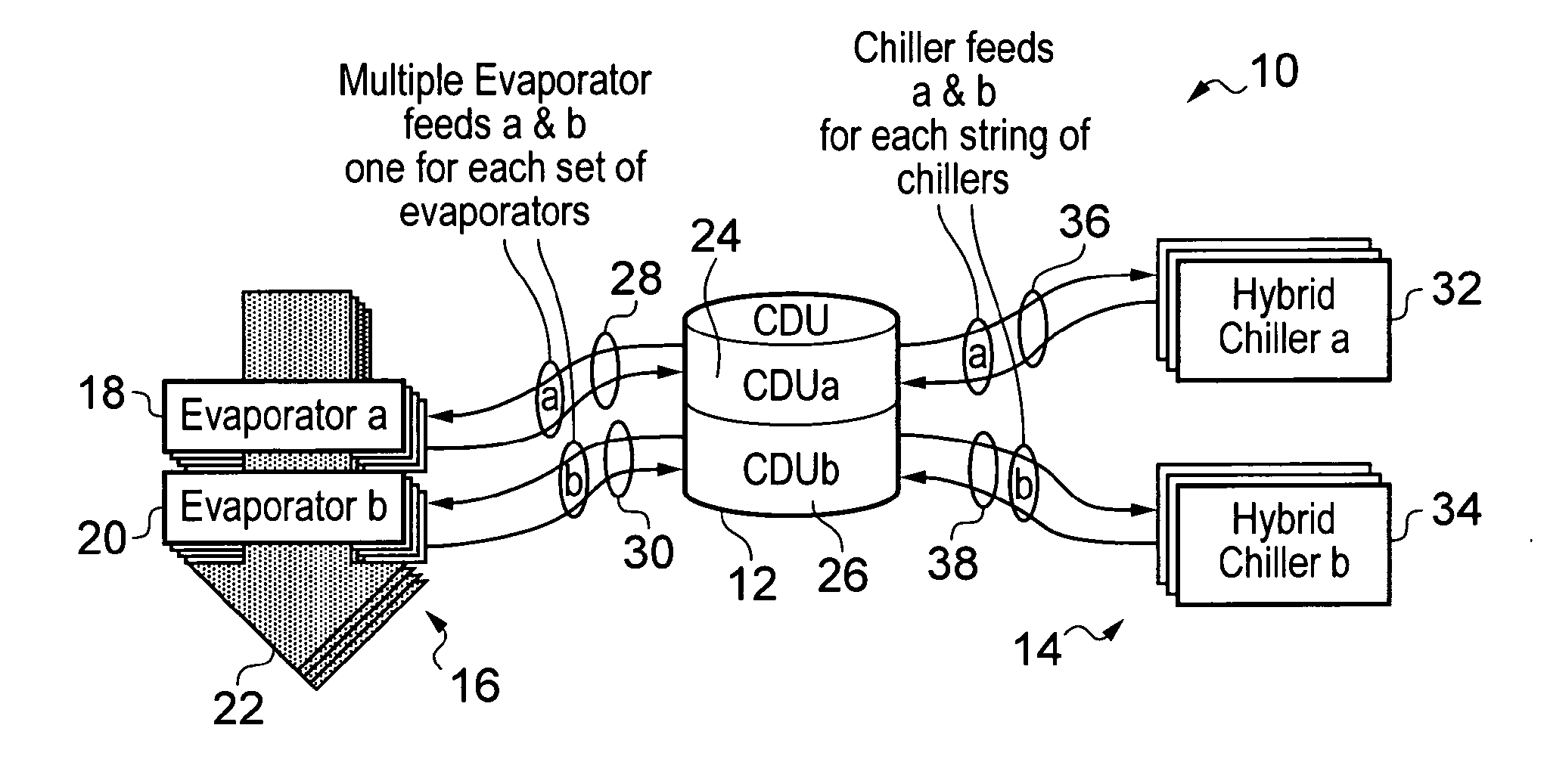
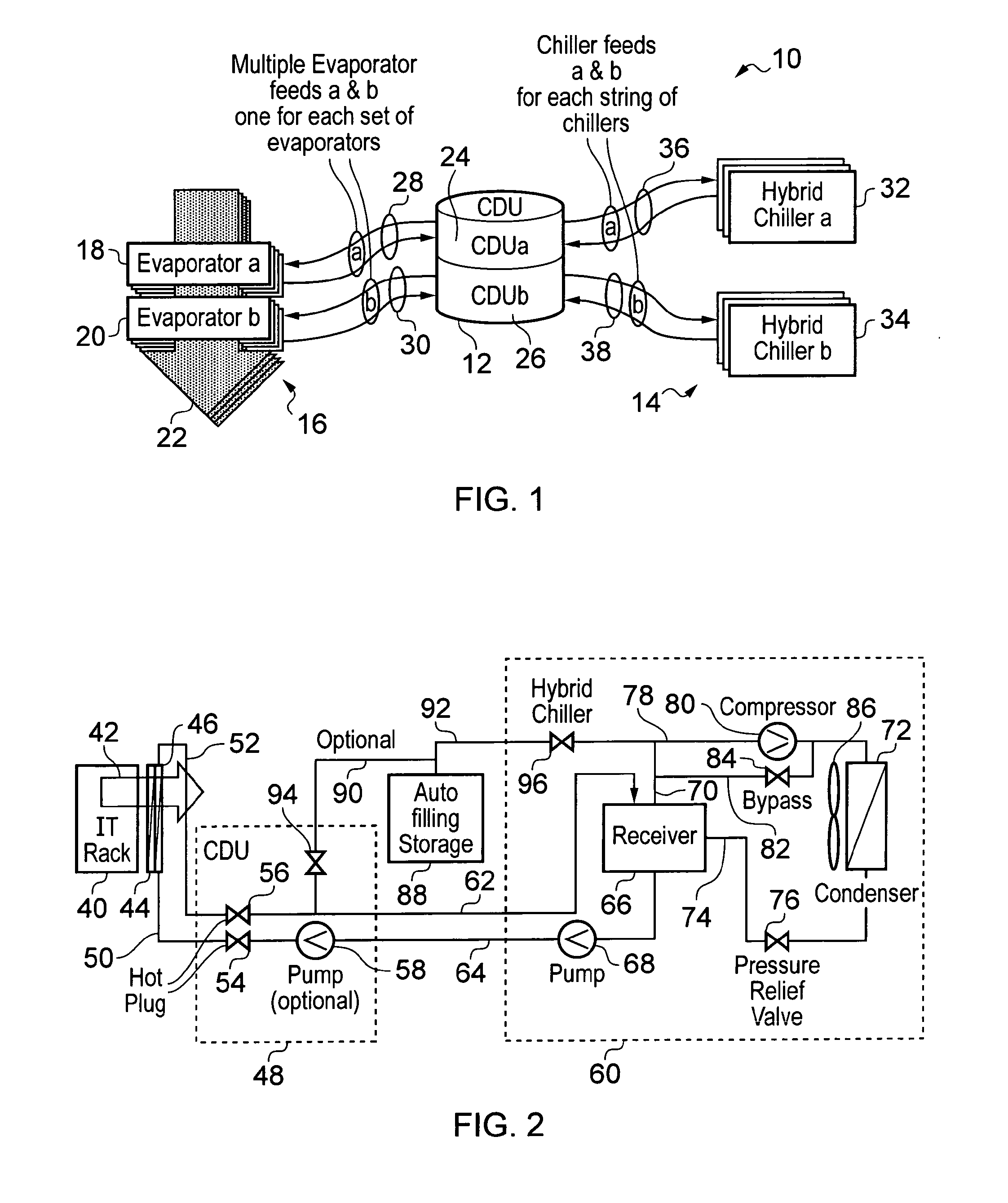
Cooling apparatus providing two independent heat exchangers (18, 20) serially arranged with respect to a heat flow (42), each heat exchanger being connected to a respective independent chiller (32, 34). The apparatus incorporates an element of redundancy in order to effect an increase in operational efficiency, by being switchable between a first operation mode in which both chillers operate in a free cooling mode and a second operation mode in which a first chiller operates in a free cooling mode and a second chiller operates in a forced cooling mode.

Description

FIELD OF THE INVENTION[0001]This invention relates to cooling equipment, e.g. for air conditioners, electrical appliances or the like, in which fluid coolant is circulated between a absorbing region where it absorbs energy from the surrounding environment and a cooling region where it emits energy to the surrounding environment.BACKGROUND OF THE INVENTION[0002]Electrical appliances, e.g. televisions, PCs, servers and the like, emit heating during operation. In the case of information technology (IT) equipment it is often necessary for operation to be continuous. Problems, e.g. malfunction, may occur if the equipment overheats, so it is important to control the temperature of the surrounding environment.[0003]Air conditioning may be used to control the temperature of a space, e.g. room, warehouse or the like, that contained heat generating equipment. Conventional air conditioning apparatus operates to cool air, which is subsequently circulated in the space to control the temperature....

Claims


Application Information

Patent Timeline
IPC IPC(8): F25B41/00
CPCF25B41/00F25B2400/06F25B2309/06F28F27/02
Inventor PEDERSEN, DANIEL RENE HAGEN
Owner LEANECO APS
Why Eureka
Try Eureka