Tessellation of patches of surfaces in a tile based rendering system

Active Publication Date: 2011-11-03
IMAGINATION TECH LTD
View PDF1 Cites 73 Cited by
  • Summary
  • Abstract
  • Description
  • Claims
  • Application Information

AI Technical Summary

Benefits of technology

[0025]The third phase re-calculates the domain points for the primitives that remain after hidden surface removal. The domain shader is then applied to these points in full i.e. vertex attributes are also calculated. The resulting primitives are then passed down the pipeline as normal. As the third phase is executed after

Problems solved by technology

The addition of a Dx11 programmable tessellation pipeline to a tile based rendering system means that it is not possi

Method used


Image

  • Tessellation of patches of surfaces in a tile based rendering system
  • Tessellation of patches of surfaces in a tile based rendering system
  • Tessellation of patches of surfaces in a tile based rendering system

Examples


Embodiment Construction

[0036]FIG. 5 illustrates the tiling phase of a proposed system for processing programmable tessellation primitives within a tile based rendering system embodying the invention. A vertex shading unit 500 and a hull shading unit 506 operate as described above for Dx11. The hull shading unit passes calculated edge tessellation factors to both a Domain Tessellation unit 510 and a connectivity tessellation unit 515. The hull shader also passes processed control point data to a domain shader 520.

[0037]The connectivity tessellation unit 515 calculates vertex indices for triangles. These indices reference the vertices generated by the action of the domain shader on the generated domain points from the domain tessellation unit. The vertex indices are passed to a cache unit 522 which caches vertex values previously generated by the domain shading unit. It should be noted that the cache is not required but the interconnected nature of the primitives that make up the tessellated patch mean that...


PUM


Abstract

A method and apparatus are provided for tessellating patches of surfaces in a tile based three dimensional computer graphics rendering system. For each tile in an image a per tile list of primitive indices is derived for tessellated primitives which make up a patch. Hidden surface removal is then performed on the patch and any domain points which remain after hidden surface removal are derived. The primitives are then shaded for display.

Description

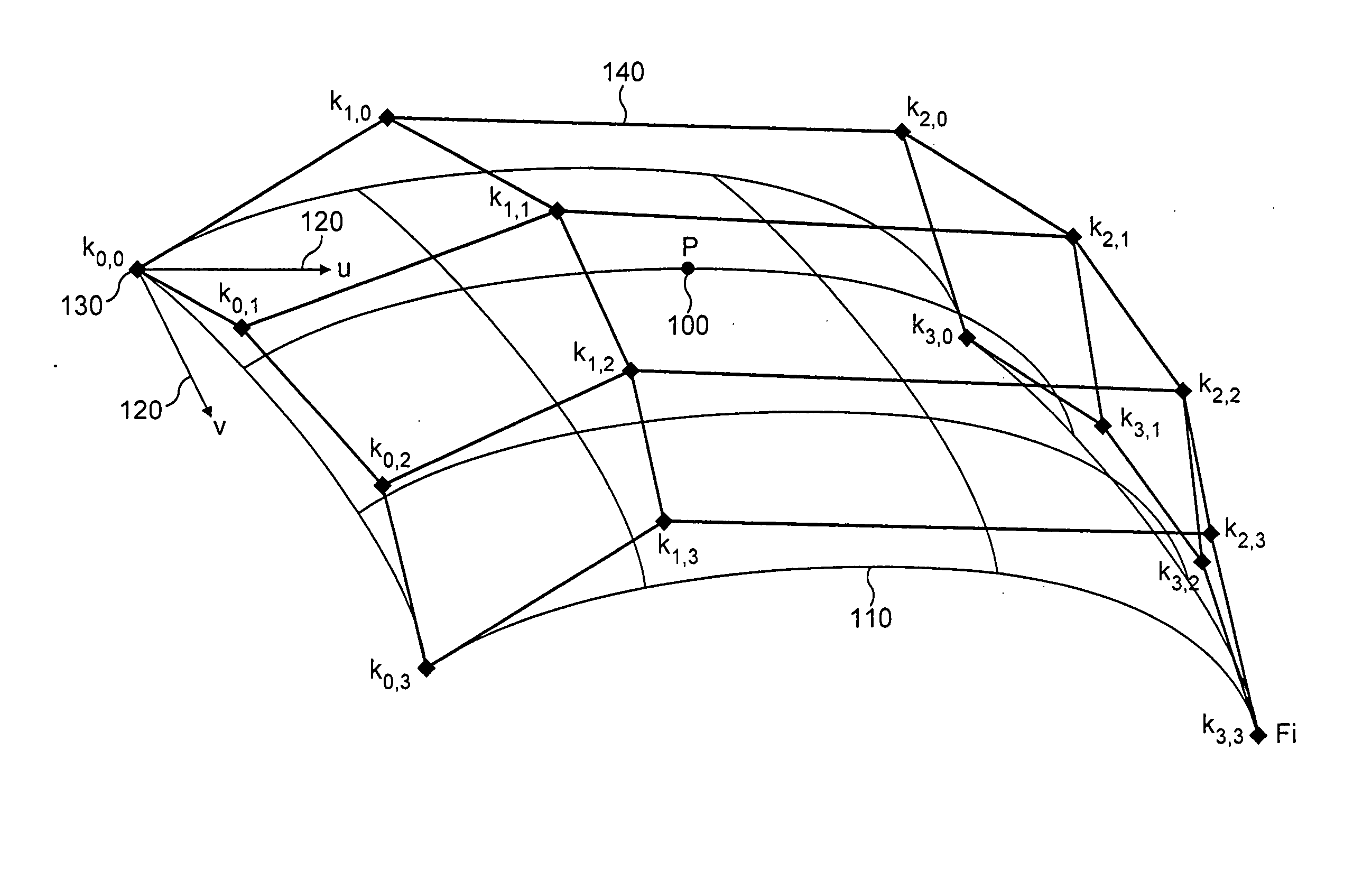
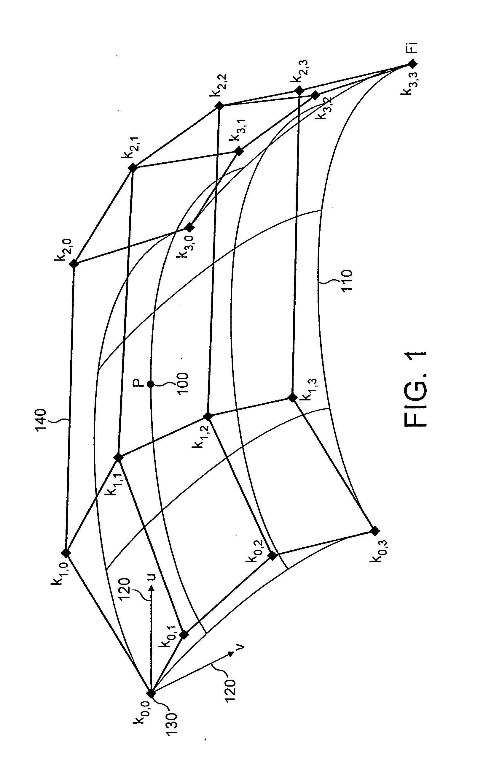
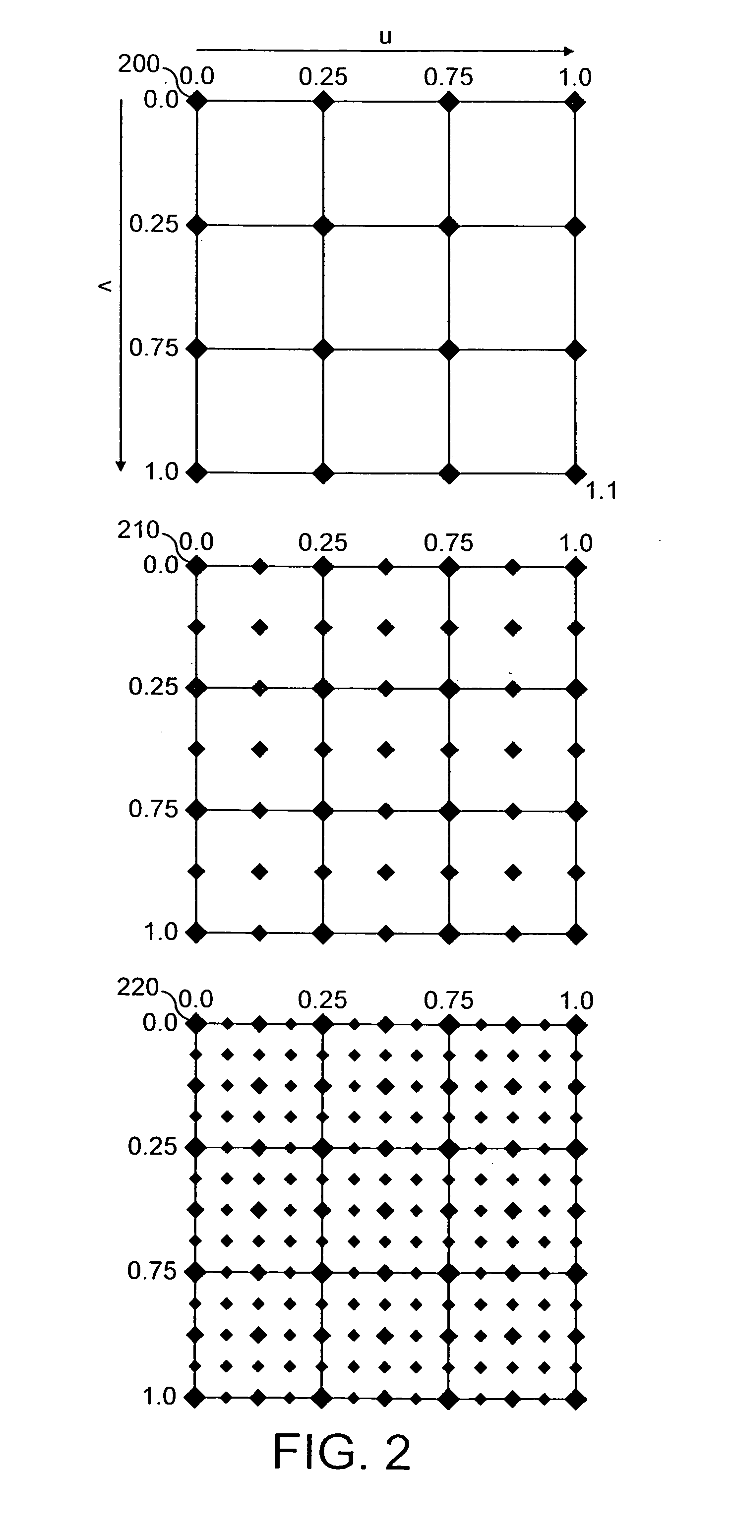
[0001]This invention relates to a three-dimensional computer graphics rendering system in particular to methods and apparatus for tessellating patches of surfaces in a tile based rendering system.BACKGROUND TO THE INVENTION[0002]High order surfaces are a well known technique within the computer graphics industry. Higher order surfaces or “patches” which are functions of polynomial equations typically define a set of control points that are used to describe the behaviour of a curved surface in terms of well known mathematical parametric relationships between a variable ‘t’ (for a curve that is plotted in two dimension) or two variables u, v (for a curve that is plotted in three dimensions) and the surface of a curve. FIG. 1 illustrates a Bezier patch which is a well known example of a high order surface type used within 3D computer graphics. A point P 100, on the Bezier surface 110 is defined by the function of the parametric coordinates u, v 120 (also known as the domain co-ordinate...

Claims


Application Information

Patent Timeline
IPC IPC(8): G06T17/20
CPCG06T15/005G06T15/40G06T17/20
Inventor HOWSON, JOHN WILLIAM
Owner IMAGINATION TECH LTD
Why Eureka
Try Eureka