Wind energy installation comprising a seawater or brackish water desalination plant

Inactive Publication Date: 2006-04-18
AERODYN ENG GMBH
View PDF14 Cites 21 Cited by
  • Summary
  • Abstract
  • Description
  • Claims
  • Application Information

AI Technical Summary

Benefits of technology

[0009]The essence of the invention is to use most of the available kinematic energy of a wind power plant directly for driving pump units, which produce the necessary pressure and volume flow of the sea or brackish water for a reverse osmosis plant. All of the functional elements such as untreated water reservoir, filter unit, pump units,

Problems solved by technology

This type pf conversion chain means double efficiency los

Method used


Image

  • Wind energy installation comprising a seawater or brackish water desalination plant
  • Wind energy installation comprising a seawater or brackish water desalination plant

Examples


Embodiment Construction

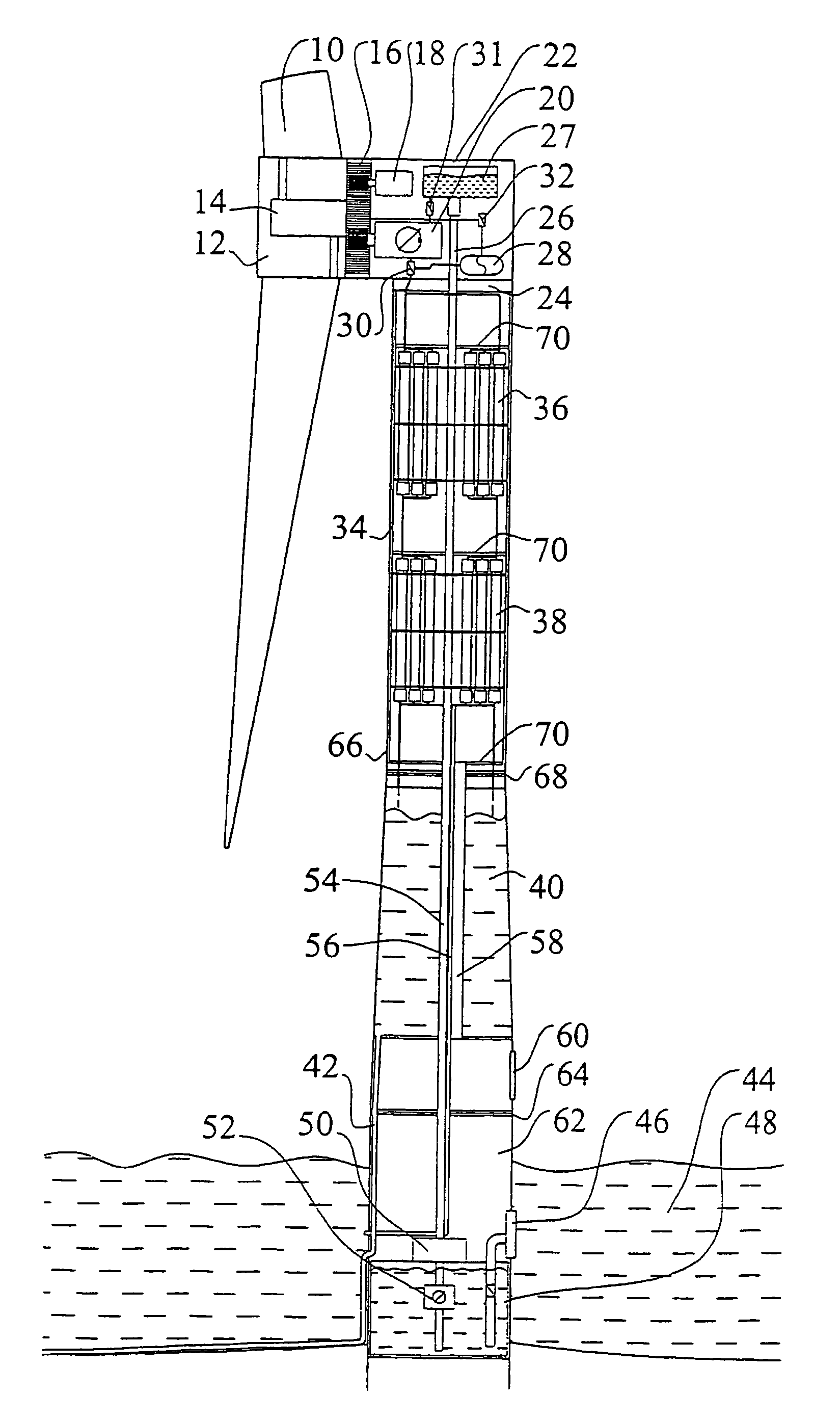
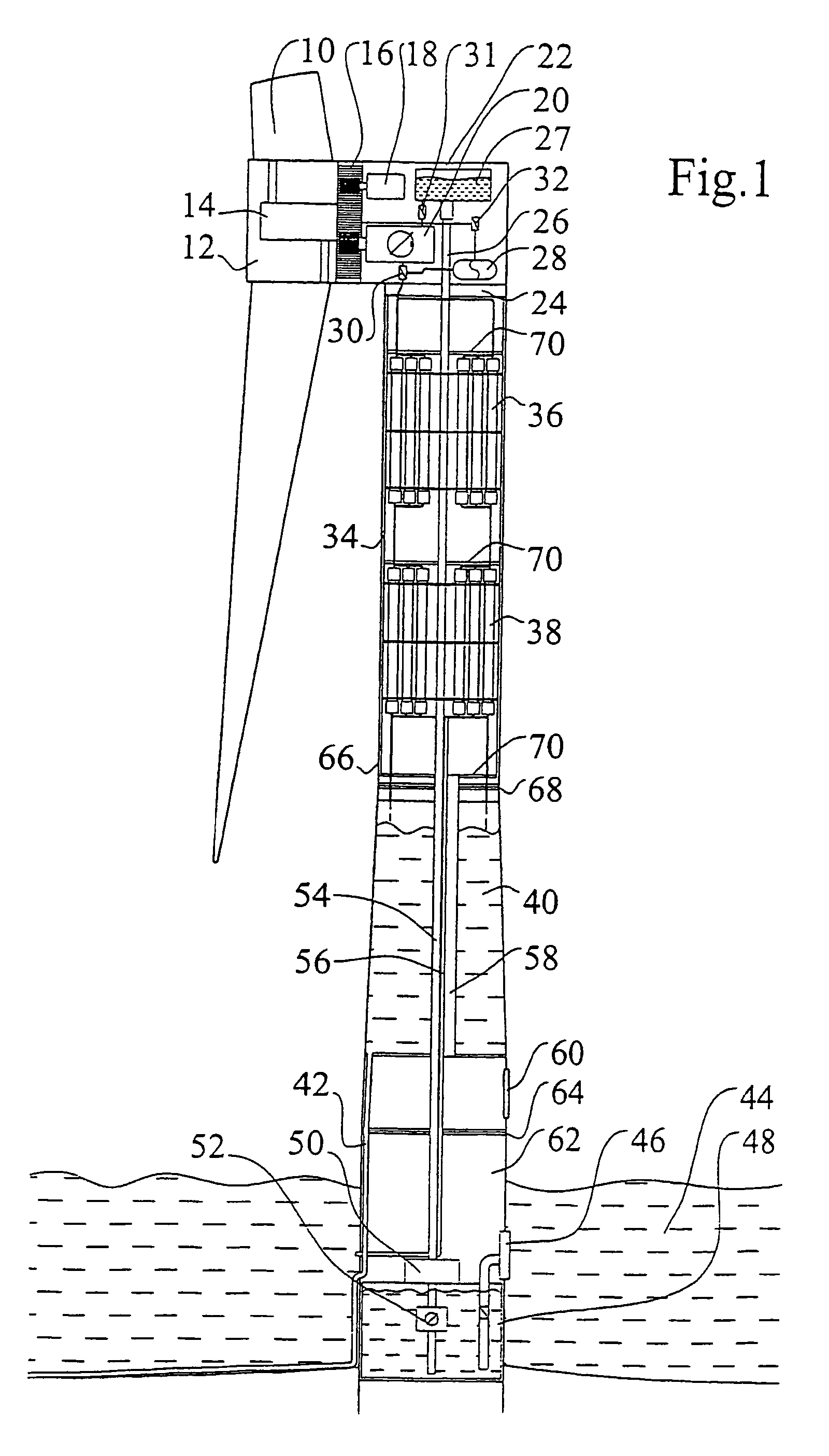
[0018]The energy transformation of the wind power plant from translatory air movement to energy of rotation takes place by means of the rotor blades 10 which are pivotally mounted on the rotor hub 12, and whose setting angle can be modified by means of the blade adjustment 14. By means of the gear 16 which is driven on the rotor side by the hub 12, the speed of the driven shafts is raised to 1500 to 3000 min−1. At the rapidly rotating driven shafts are driven, an auxiliary generator 18 and one or more pressure pumps 20. The electric power generated by the auxiliary generator 18 is temporarily stored by a battery supplying the regulating device.

[0019]These components are located in the gondola 22 of the wind power plant continuously oriented in accordance with the variable wind direction by means of the wind direction tracking system 24. By means of a rotary passage 26, the sea or brackish water 44 is fed into the storage tank 27 and supplied by means of valve 31 to the pressure pump...


PUM

PropertyMeasurementUnit
Pressureaaaaaaaaaa
Areaaaaaaaaaaa

Abstract

A wind energy installation having a tower, a gondola supported by the tower, a rotor mounted in the gondola, and at least one pressure pump that is mechanically driven by the rotor and that feeds a raw water-treating reverse osmosis plant, the components of the reverse osmosis plant being arranged within the tower.

Description

PRIOR APPLICATIONS[0001]This application bases priority on International Application No. PCT / DE02 / 00278, filed Jan. 28, 2002, which in turn bases priority on German Application No. DE 101 05 181.6, filed Feb. 6, 2001.BACKGROUND OF THE INVENTION[0002]1. Field of the Invention[0003]This invention relates to a wind power plant having a tower, a gondola carried by the latter, a rotor mounted in the gondola and at least one pressure pump, feeding a reverse osmosis plant, and mechanically driven by the rotor.[0004]2. Description of the Prior Art[0005]Wind power plants used for generating electric power are known in numerous different constructions. In addition, sea water desalination plants are known which desalinate sea or brackish water, usually employing fossil energy sources. Also in the case of electrically operated plants working according to the reverse osmosis process, use is normally made of electric power generated using fossil fuels.[0006]To permit the use of renewable energy s...

Claims


Application Information

Patent Timeline
IPC IPC(8): B01D61/10C02F1/44F03D9/02B01D61/02F03D1/06F03D9/00F03D9/10F03D9/25F03D9/28F03D13/20
CPCF03D9/00F03D9/02Y02E10/721F05B2220/62F03D13/22Y02W10/33F03D9/10Y02A20/141Y02E10/728F03D9/11F03D9/28F03D9/25Y02E10/72Y02P80/10Y02E70/30
Inventor SIEGFRIEDSEN, SONKE
Owner AERODYN ENG GMBH
Why Eureka
Try Eureka