Printing apparatus and inkjet method

a printing apparatus and inkjet technology, applied in the field of inkjet printing, can solve the problems of large amount of evaporated ink, increased marked increase in humidity in the hot air, so as to improve the drying ability and improve the drying efficiency of ink.

Inactive Publication Date: 2011-11-03
CANON KK
View PDF16 Cites 14 Cited by
  • Summary
  • Abstract
  • Description
  • Claims
  • Application Information

AI Technical Summary

Benefits of technology

[0007]An object of the present invention is to provide an apparatus and method wherein improvements of drying ability and reduction of consumed power are concurrently achieved by improving the ink drying efficiency.

Problems solved by technology

However, when hot air is circulated the humidity of the hot air generally increases due to vapor evaporated from the printed image.
In particular, the amount of this evaporated ink becomes large and the increase of humidity in the hot air becomes marked when continuously printing multiple pages of print media and when performing a high duty printing wherein the ink ejected per unit area is increased.
For this reason, drying of the image printed on the print medium becomes insufficient, moisture within the print medium increases, and because of this a problem occurs wherein the drying efficiency is decreased.

Method used


Image

  • Printing apparatus and inkjet method
  • Printing apparatus and inkjet method
  • Printing apparatus and inkjet method

Examples


embodiment 1

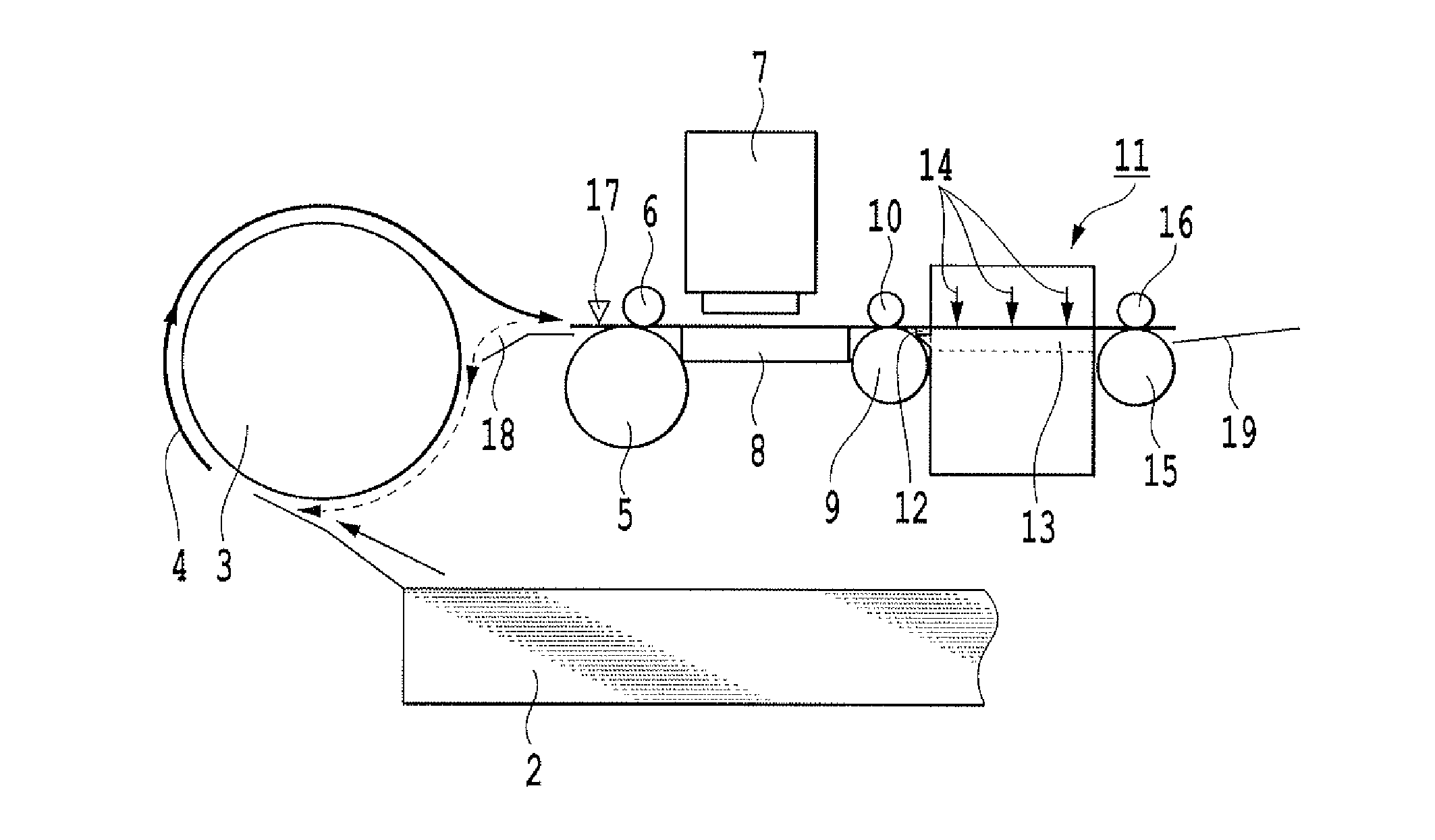
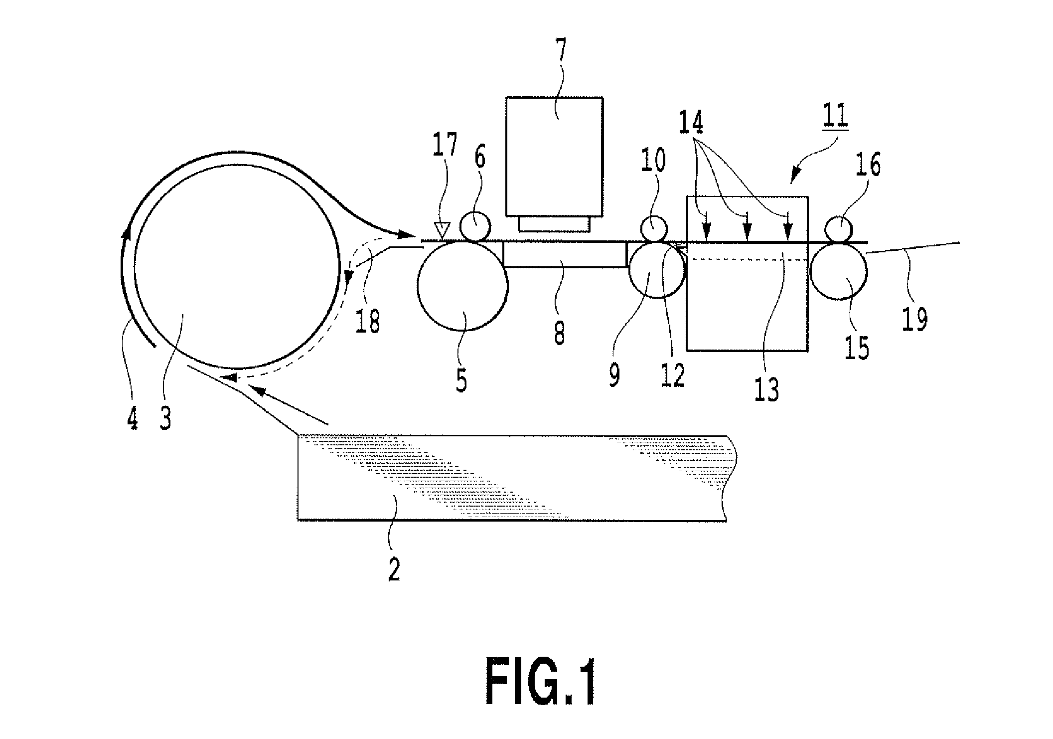
[0031]FIG. 1 is a schematic view of the inkjet printing apparatus according to a first embodiment of the present invention, and in particular the structure along the print medium conveyance path. It should be noted that the present invention can also be applied in printing apparatuses other than inkjet type apparatuses, in which drying of the print medium after printing is necessary for fixation.

[0032]In FIG. 1 the print medium is a cut sheet, which can be set to a maximum of 250 sheets inside a sheet feeding cassette 2, and is picked up and fed one sheet at a time by a sheet feeding roller and separation mechanism (not shown). A U-turn conveying unit 3 conveys, along with an unshown conveyance roll, the print medium in the direction shown by the arrowed line 4. The U-turn conveying unit 3 also functions as a double-side inversion unit, as described later. The print medium, which is conveyed along the direction of the arrow 4, is held between a LF roller 5 and a pinch roller 6, and ...

embodiment 2

[0069]In the first embodiment described above the temperature of the silicon rubber heater is measured by a preheating temperature sensor (thermistor), and based on this measured temperature, the temperature of the print medium passing over the silicon rubber heater is specified and acquired by experiment. In contrast to this, in a second embodiment of the present invention, without providing a sensor that measures the temperature of the silicon rubber heater, a sensor is provided that directly measures the temperature of the silicon rubber heater or the temperature of the print medium conveyed over it. Only the configuration of this print medium temperature detection that differs will be explained below.

[0070]FIG. 13A is a perspective view that illustrates the fixation unit of a second embodiment of the present invention, and FIG. 13B is a perspective view of the top cover unit 300 of the fixation unit, viewed from the lower side. In these figures the top cover 302 has an analogous...

embodiment 3

[0075]The above described first and second embodiments provide a mechanism that detects the temperature and humidity of the hot air, and the temperature of the preheater (the silicon rubber heater). However, even without detecting the temperature of the preheater or the print medium it is possible to control the temperature of the preheater that heats the print medium based on the dew point temperature and the ambient temperature. A third embodiment of the present invention has a simplified configuration in which the sensor that detects the temperature of the preheater is omitted.

[0076]In the apparatus of the present embodiment, a temperature sensor is provided inside the apparatus in order to check internal temperature rise and compensate for variation in the ejection amount with temperature. Although omitted from the figure, a thermistor is provided on the main board of the apparatus, which enables temperature measurement inside the mechanism. By providing this internal temperatur...


PUM


Abstract

In a printing apparatus improvement of drying ability and reduction of consumed power are concurrently achieved by improving the efficiency of drying ink. More concretely, hot air is blown onto a print medium printed by ink, and a portion of the blown hot air is recovered and blown again. Before the hot air is blown, the print medium is heated by a preheating unit, making it higher than the dew point temperature of the blown hot air.

Description

BACKGROUND OF THE INVENTION[0001]1. Field of the Invention[0002]The present invention is related to a technical field that concerns inkjet printing, and the like, that are capable of fixing, by hot air, an image printed by the application of ink to a print medium.[0003]2. Description of the Related Art[0004]Printing apparatuses, such as inkjet printers and the like, that facilitate the fixation of a printed image by blowing hot air onto an image printed by the application of ink onto a print medium, are known in the prior art. As one such printing apparatus, Japanese Patent Laid-open No. 2001-071474 discloses an apparatus that circulates hot air by returning to a blowing mechanism, provided with an air heating heater and a fan, hot air that has been blown from the blowing mechanism onto an image printed on a print medium. This type of hot air circulation structure can reduce the heat energy of a heater that is necessary for regulating air to a prescribed temperature, and has an adva...

Claims


Application Information

Patent Timeline
Patent Type & Authority Applications(United States)
IPC IPC(8): B41J2/01
CPCB41J11/002B41J11/0022
Inventor YAMAMOTO, KOSUKESAITO, TETSUYUKAWATOKO, NORIHIROIWASAKI, OSAMU
Owner CANON KK
Why Eureka
Try Eureka