Outer joint member for fixed constant velocity universal joint

a technology outer joints, which is applied in the direction of mechanical devices, other domestic objects, couplings, etc., can solve the problems of affecting the quality of the finished product, the occurrence of abrasion, deformation, and the inability to undergo cold forging, so as to reduce the manufacturing cost of constant velocity universal joints using the outer joint members, increase the yield, and reduce the manufacturing cost of outer joints

Active Publication Date: 2011-11-03
NTN CORP
View PDF13 Cites 4 Cited by
  • Summary
  • Abstract
  • Description
  • Claims
  • Application Information

AI Technical Summary

Benefits of technology

[0023]On the outer joint member for a fixed type constant velocity universal joint according to the present invention, it is unnecessary to perform conventional finishing processes such as a cutting process and a grinding process after cold forging. Thus, yields can be increased, and manufacturing cost of the outer joint member, by extension, manufacturing cost of the constant velocity universal joint using the outer joint member can be reduced.
[0024]Further, through provision of the cup-inlet chamfer, even when the constant velocity universal joint forms an operating angle, an opening rim of the outer joint member is prevented from interfering with the shaft mounted to the inner joint member. Through provision of the track-inlet chamfer, an effective range in which the torque transmitting ball moves can be effectively secured. Through provision of the track chamfers, chipping of the track-groove edge portions can be prevented.
[0025]Through provision of the center hole into the end surface of the shaft section, properties of post processes (processing of a male spline, a male thread, and the like provided to the shaft) with use of the center hole can be enhanced. In particular, simultaneously with cold forging of the center hole, cold forging can be performed on the other parts. With this, the center hole constitutes a reference surface with respect to an axial position of the outer joint member, and hence the outer joint member can be molded at high axial-position accuracy. Thus, the outer joint member of the present invention is optimum as an outer joint member for a fixed type constant velocity universal joint of the BJ type that requires high axial-position accuracy.
[0026]When the finishing process after heat treatment is performed on the radially inner spherical-surface portions of the cup section, required high accuracy can be satisfied. Thus, a product (outer joint member) of high quality can be molded.
[0027]When the slit groove is formed in each of the radially inner spherical-surface portions and the width dimension of the slit groove is set to range from 5% to 30% of the maximum width dimension of each of the radially inner spherical-surface portions, a product (outer joint member) of high accuracy and high quality can be stably produced at low cost.
[0028]When each of the track grooves has such a lateral-sectional Gothic arch shape as to be held in angular contact with the ball and the angle formed by the angular contact is set to range from 35° to 45°, the contact state of the ball can be stabilized. As a result, a constant velocity universal joint can be structured, which is capable of smooth transmission of a rotational force and is excellent in durability.

Problems solved by technology

The machine-structural carbon steel of the outer joint member used for the constant velocity universal joints is a hard material, and hence difficult to undergo cold forging.
Thus, materials to be forged are limited.
Thus, abrasion, deformation, and breakage of the die are liable to occur.
Thus, conventionally, there has been such a technic that general cold forging is unavailable with respect to the outer al common sense race as a mechanical component, and hence there has been no idea of performing cold forging thereon.
As a result, man-hours of the post processes are increased, which leads to an increase in manufacturing cost.

Method used


Image

  • Outer joint member for fixed constant velocity universal joint
  • Outer joint member for fixed constant velocity universal joint
  • Outer joint member for fixed constant velocity universal joint

Examples


Embodiment Construction

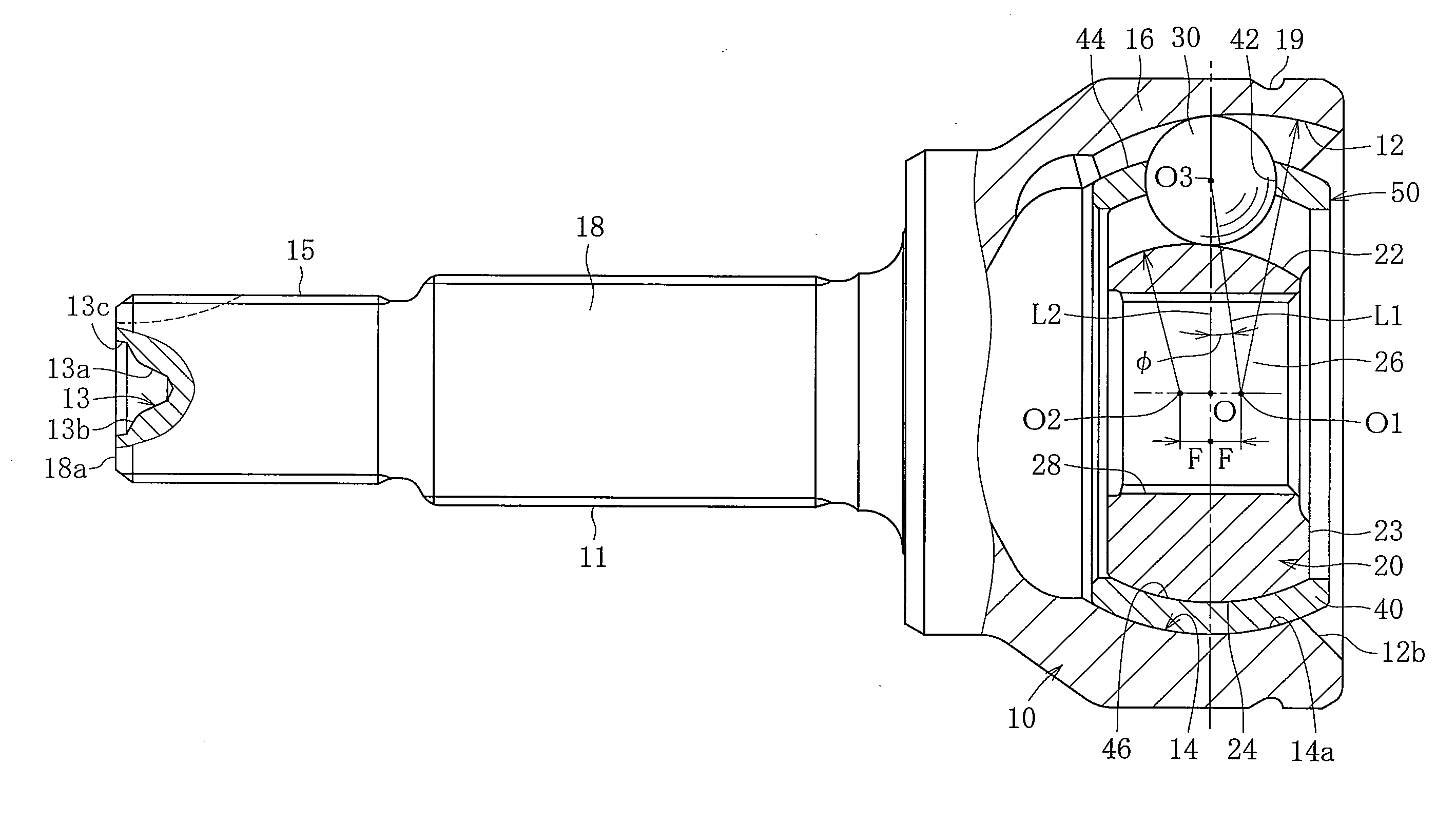
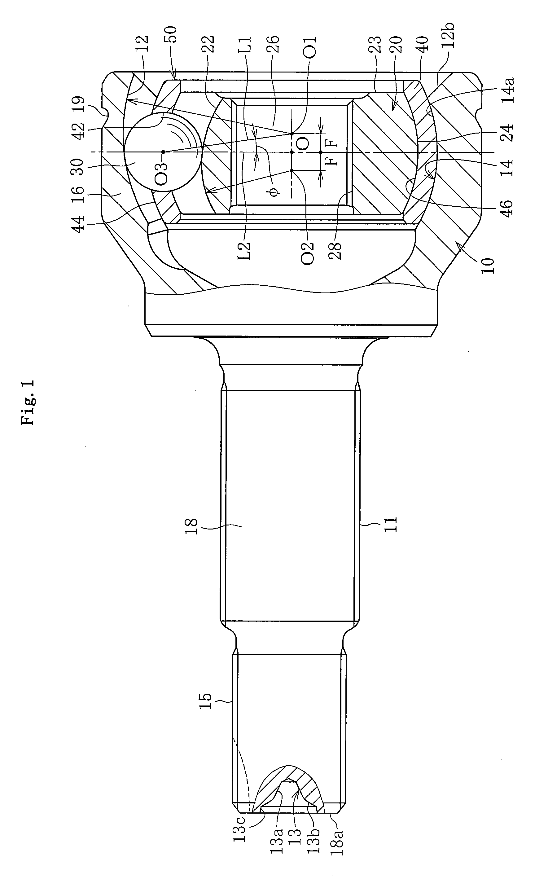
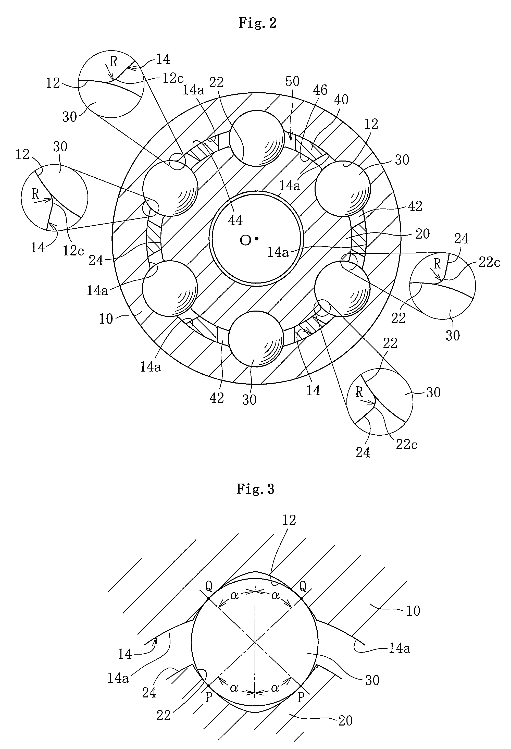
[0053]In the following, description is made of an embodiment of the present invention with reference to FIGS. 1 to 19. FIGS. 1 and 2 illustrate a fixed type constant velocity universal joint using an outer joint member according to the present invention. The fixed type constant velocity universal joint is of a Birfield type, and includes, as main components, an outer race 10 as an outer joint member, an inner race 20 as an inner joint member, balls 30, and a cage 40. The fixed type constant velocity universal joint has a structure in which an interior component 50 including the inner race 20, the balls 30, and the cage 40 is housed in the outer race 10 so as to be capable of angular displacement.

[0054]The outer race 10 is made of machine-structural carbon steel, and has a cup-like shape so as to open at one end and has a radially inner surface 14 equiangularly provided with a plurality of track grooves 12 extending in an axial direction. Note that, parts between the track grooves ad...


PUM


Abstract

Provided is an outer joint member for a fixed type constant velocity universal joint, the outer joint member contributing to reduction of the number of man-hours through reduction of the number of post processes after a forging process, and to an increase in yield, and reduction of manufacturing cost. The outer joint member for a fixed type constant velocity universal joint includes a cup section (16) and a shaft section (18) extending in an axial direction from a bottom portion of the cup section (16). The outer joint member is made of machine-structural carbon steel. The following portions of the outer joint member are finished by cold forging: track grooves (12); radially inner spherical-surface portions (14a); a cup-inlet chamfer (12b); track chamfers (12c); track-inlet chamfers (12a); a part except for a boot fixing portion (19) on a radially outer surface of the cup section (16); and a center hole (13) at an end surface (18a) of the shaft section (18).

Description

TECHNICAL FIELD[0001]The present invention relates to an outer joint member for a fixed type constant velocity universal joint.BACKGROUND ART[0002]Examples of constant velocity universal joints include a fixed type constant velocity universal joint which allows only angular displacement and a plunging type constant velocity universal joint which allows not only the angular displacement but also axial displacement. Examples of the fixed type constant velocity universal joint include a Birfield type (BJ) and an undercut free type (UJ), and examples of the plunging type constant velocity universal joint include a double offset type constant velocity universal joint (DOJ) and a cross groove type constant velocity universal joint (LJ).[0003]The fixed type constant velocity universal joint of the BJ type includes an outer race as an outer joint member having an inner spherical surface equiangularly provided with a plurality of track grooves formed along an axial direction, an inner race a...

Claims


Application Information

Patent Timeline
Patent Type & Authority Applications(United States)
IPC IPC(8): F16D3/24F16D3/16B21K1/14F16D3/20F16D3/2237F16D3/2245
CPCB21K1/762B21K1/765F16D3/223F16D3/2245F16D2003/22309F16D2250/0023
Inventor KOBAYASHI, MASAZUMIYAMAZAKI, KISAOISHIJIMA, MINORU
Owner NTN CORP
Why Eureka
Try Eureka