Contactless power supply system and control method thereof

a power supply system and contactless technology, applied in non-electric variable control, process and machine control, instruments, etc., can solve problems such as inability to detect, and achieve the effect of quick detection when

Active Publication Date: 2011-11-03
TOYOTA JIDOSHA KK
View PDF124 Cites 114 Cited by
  • Summary
  • Abstract
  • Description
  • Claims
  • Application Information

AI Technical Summary

Benefits of technology

[0006]The invention provides a system and control method thereof, which is capable of quickly detecting when

Problems solved by technology

However, if an object or a person approaches the power transmitting apparatu

Method used


Image

  • Contactless power supply system and control method thereof
  • Contactless power supply system and control method thereof
  • Contactless power supply system and control method thereof

Examples


Embodiment Construction

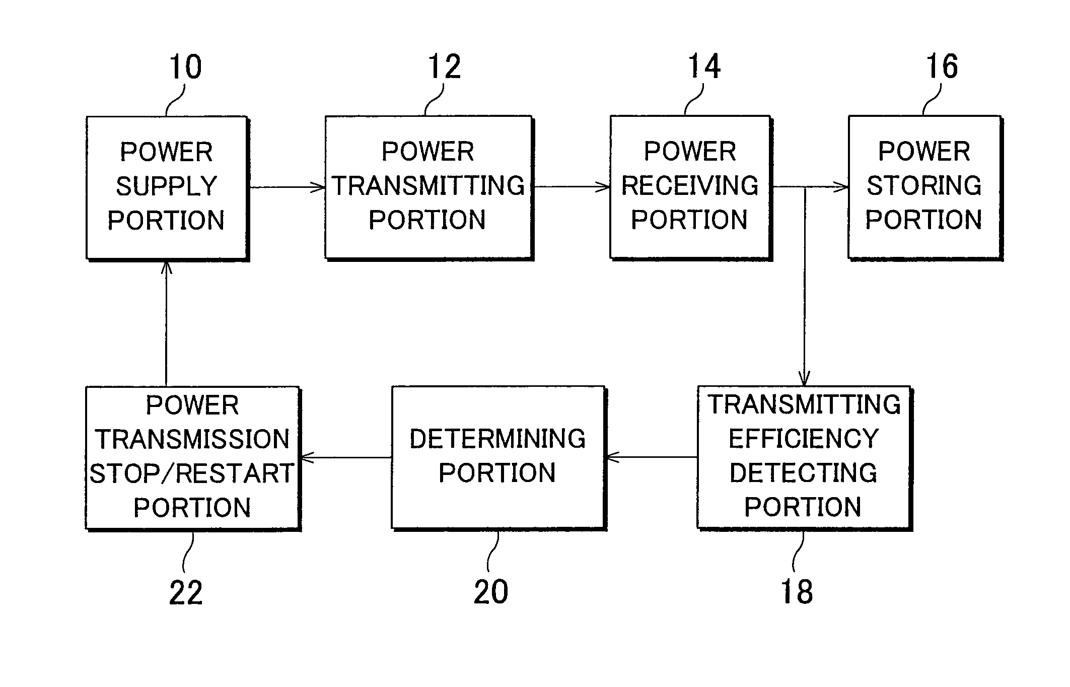
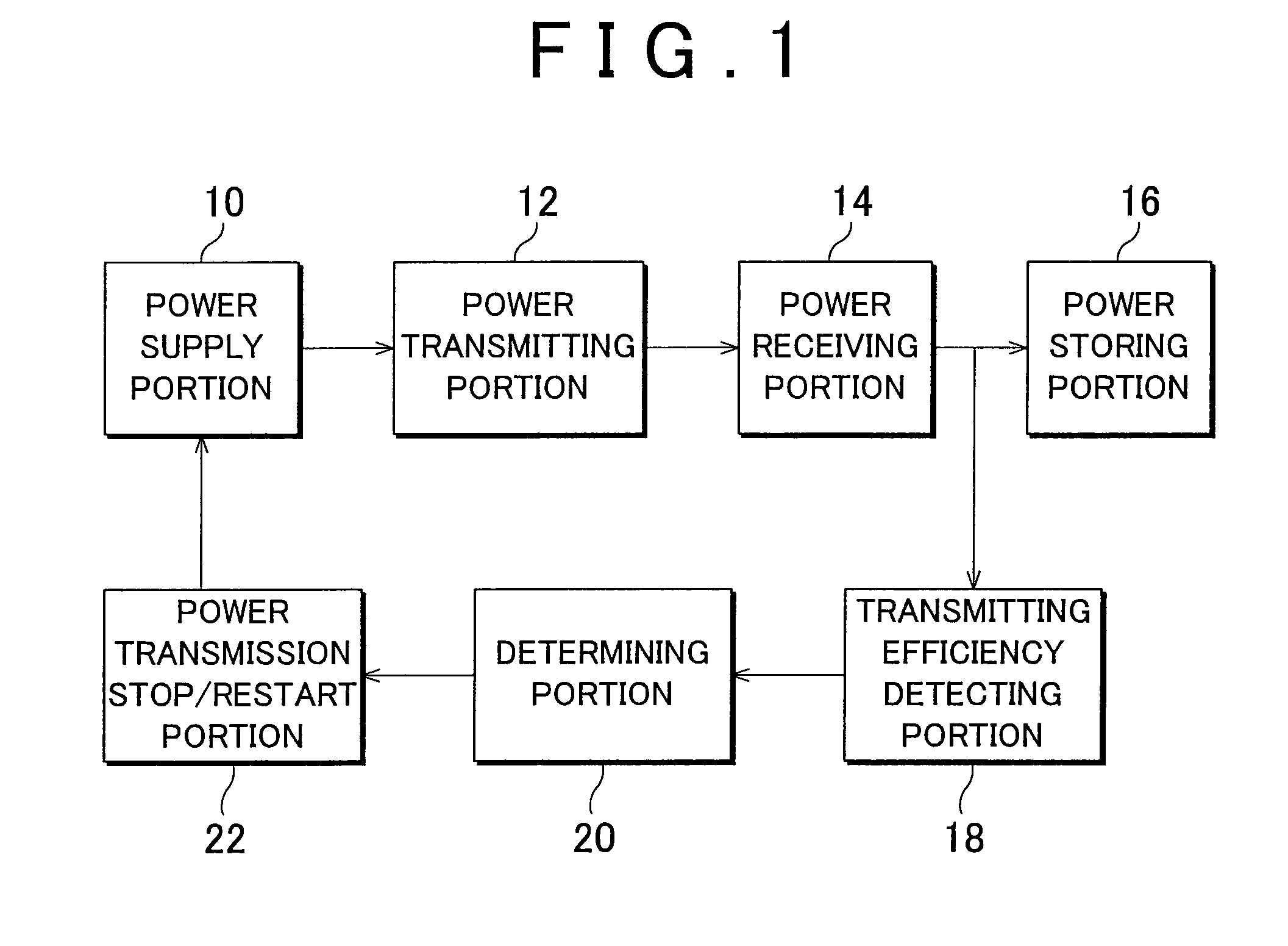
[0036]FIG. 1 is a configuration block diagram of a power supply system according to the first example embodiment of the invention. Power from a power supply portion 10 such as a commercial power supply is supplied to a power transmitting portion 12.

[0037]The power transmitting portion 12 is formed by a power transmitting coil and a power transmitting side resonance coil.

[0038]A power receiving portion 14 is formed by a power receiving coil and a power receiving side resonance coil, and is coupled to the power transmitting side by electromagnetic field resonance. Power is transmitted and received without contact between the power transmitting portion 12 and the power receiving portion 14. The power receiving portion 14 supplies the power received from the power transmitting portion 12 to a power storing portion 16.

[0039]The power storing portion 16 rectifies the power from the power receiving portion 14 and supplies it to a secondary battery to charge the secondary battery.

[0040]A tr...


PUM


Abstract

Power is contactlessly supplied from a power transmitting portion to a power receiving portion. A transmitting efficiency detecting portion detects the transmitting efficiency, and a determining portion determines whether the transmitting efficiency is equal to or greater than a specified value. If the transmitted efficiency is less than the specified value, an obstruction may be present so power temporarily stops being transmitted. Power is then periodically transmitted with a minute power and the efficiency is detected. If the efficiency is equal to or greater than the specified value, power starts to be transmitted again with regular power.

Description

BACKGROUND OF THE INVENTION[0001]1. Field of the Invention[0002]The invention relates to a power supply system and a control method thereof. More particularly, the invention relates to a countermeasure for an obstruction near a system that contactlessly supplies power.[0003]2. Description of the Related Art[0004]A non-contact power supply system that uses electromagnetic induction is known. For example, Japanese Patent Application Publication No. 2001-258182 (JP-A-2001-258182) describes one such a non-contact power transmitting apparatus. FIG. 13 shows the structure of this related art. This power transmitting apparatus contactlessly supplies power between a main body 1 that has a first coil 6 which receives power supplied from a commercial power supply, and a terminal 2 that has a second coil 7 which is coupled by electromagnetic induction to the first coil 6. A temperature increase preventing device which automatically stops the supply of power to the terminal 2 when a temperature...

Claims


Application Information

Patent Timeline
IPC IPC(8): G06F1/28H02J7/00
CPCH02J5/005H02J7/025H02J17/00B60L11/182B60L11/1833Y02T90/122Y02T90/125Y02T90/12Y02T90/121Y02T90/14Y02T10/7005Y02T10/7072B60L53/12B60L53/36B60L53/124H02J50/12H02J50/60H02J50/90Y02T10/70Y02T10/92
Inventor AMANO, YASUSHIICHIKAWA, SHINJI
Owner TOYOTA JIDOSHA KK
Why Eureka
Try Eureka