Thermally Conductive Grease and Methods and Devices in Which Said Grease is Used

a technology of thermal conductivity and grease, applied in the field of grease, can solve the problems of affecting the performance generating heat in the operation of the (opto)electronic component, and negatively affecting the mean time between failures

Active Publication Date: 2011-11-10
DOW SILICONES CORP
View PDF4 Cites 10 Cited by
  • Summary
  • Abstract
  • Description
  • Claims
  • Application Information

AI Technical Summary

Benefits of technology

[0007]A grease comprises a combination of polyorganosiloxanes and a thermally conductive filler. The grease is useful as a TIM.

Problems solved by technology
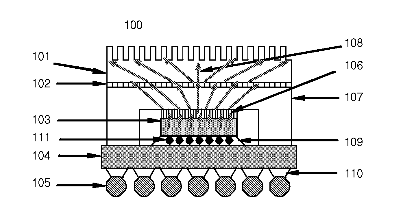
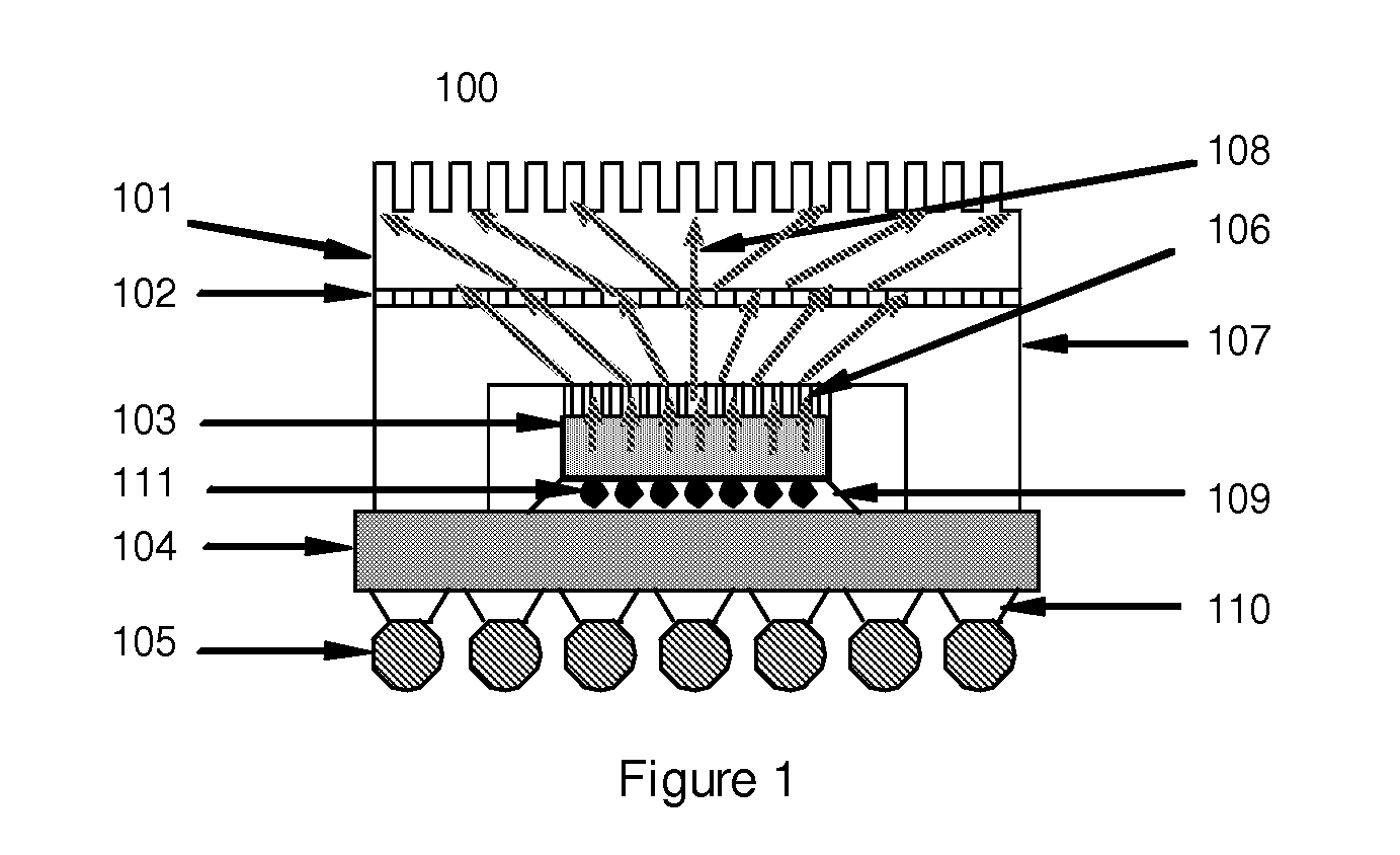
However, the operation of an (opto)electronic component generates heat.
Excessive temperatures can adversely affect performance of the (opto)electronic component and operation of the device associated therewith and negatively impact mean time between failures.
Surfaces of the (opto)electronic component and the heat sink are typically not completely smooth, therefore, it is difficult to achieve full contact between the surfaces.
Air spaces, which are poor thermal conductors, appear between the surfaces and increase impedance.

Method used


Image

  • Thermally Conductive Grease and Methods and Devices in Which Said Grease is Used
  • Thermally Conductive Grease and Methods and Devices in Which Said Grease is Used
  • Thermally Conductive Grease and Methods and Devices in Which Said Grease is Used

Examples


example 1

Preparation of Grease

[0082]Grease samples were prepared by mixing the ingredients described in Table 1. To make samples 1, and 2, mixing was performed under ambient conditions for 30 seconds at 3500 rpm in Hauschild centrifugal mixer (dental mixer). For samples 3 and 4, mixing was performed under ambient conditions for 30 seconds in the Hauschild centrifugal mixer, but rpm was not recorded.

TABLE 1Grease Sample Ingredients (amounts are in parts by weight)SampleComparativeSampleComparativeComparativeSampleComparativeIngredient1Sample 23Sample 4Sample 56Sample 7A1)1.71.72.01.71.700A2)1.71.71.41.71.73.43.4A3)2.002.00000A4)02.002.0002.0A5)00002.000A6)000002.00B1)51515151515151B2)26262626262626B3)18181818181818

[0083]Ingredients A1), A2) and A5) were combined in the amounts shown in Table 1 above. Visual determination showed separation, indicating that ingredient A5) was incompatible with ingredients A1) and A2). When comparative sample 5 was made, it was thicker and difficult to work with...

example 2

Evaluation of Viscosity

[0084]Viscosities of the grease samples prepared in example 1 were measured on an Ares rheometer with a 0.6 mm gap on 25 mm diameter probes under steady shear conditions. Average viscosity (Pa·s) was measured at different shear rates initially and again after aging. Samples 1 and 2 were aged at 110° C. for 56 days. Samples 3 and 4 were aged at 85° C. and 85% relative humidity. Sample 3 was aged for 34 days, and sample 4 was aged for 20 days, under these conditions. Sample 5 was aged by heating at 150° C. for 3 days, 8 days, and 25 days. Sample 6 was aged by heating at 150° C. for 3 days and 8 days. For each sample, viscosity was measured initially and then after aging.

TABLE 2Results for Sample 1 and Comparative Sample 2Sample0.5 s−1 initial0.5 s−1 aged1349179792 (comp)30099649

[0085]Sample 1 and comparative sample 2 show upon aging at 110° C., viscosity measured at a shear rate of 0.5 s−1 increased less for the sample that contained a compatible poly(dimethylsi...

example 3

Evaluation of Thermal Performance

[0087]The grease samples prepared in example 1 were evaluated for thermal impedance according to ASTM D5470. Thermal impedance was measured using a Hitachi guarded hot plate at 50° C. An error of + / −˜0.03 was assumed. The results showed that sample 1 had a thermal impedance of 0.057 C-cm2 / W and Comparative Sample 2 had a thermal impedance of 0.053 C-cm2 / W under these test conditions.


PUM

PropertyMeasurementUnit
particle sizeaaaaaaaaaa
molar ratioaaaaaaaaaa

Abstract

A thermally conductive grease includes 2 vol % to 15 vol % of a combination of three polyorganosiloxanes and 65 vol % to 98 vol % of a thermally conductive filler. The grease may be used as a thermal interface material for dissipating heat from (opto)electronic devices, in both TIM1 and TIM2 applications.

Description

CROSS REFERENCE TO RELATED APPLICATIONS[0001]This application claims the benefit of U.S. Provisional Patent Application No. 61 / 160,398 filed 16 Mar. 2009 under 35 U.S.C. §119 (e). U.S. Provisional Patent Application No. 61 / 160,398 is hereby incorporated by reference.STATEMENT REGARDING FEDERALLY FUNDED RESEARCH[0002]None.FIELD OF THE INVENTION[0003]A thermally conductive grease (“grease”), methods for preparation and use of the grease, and devices containing the grease are disclosed. More particularly, this invention relates to a grease including a combination of polyorganosiloxanes having a thermally conductive filler dispersed therein. The grease may be used as a thermal interface material (“TIM”). The grease is useful in both TIM1 applications (where the grease is in direct contact with a heat generating component) and TIM2 applications (where the grease contacts a surface of a heat dissipator, but does is not in direct contact with the heat generating component).BACKGROUND[0004]...

Claims


Application Information

Patent Timeline
Patent Type & Authority Applications(United States)
IPC IPC(8): F28D15/00B21D53/02C09K5/00
CPCC08G77/18C08G77/20C08G77/70C08L83/04C09K5/14Y10T29/4935C08L83/00C08L2666/54C08K3/08
Inventor BHAGWAGAR, DORAB EDULHA, DAVIDNICOL, SARAHSU, KAI
Owner DOW SILICONES CORP
Why Eureka
Try Eureka