Low power digital phase lock loop circuit

a low-power, phase lock loop technology, applied in the direction of phase difference detection of angle, automatic control, electrical equipment, etc., can solve problems such as noise, and achieve the effect of increasing the overall power usage of conventional dpll circuit 100 and consuming a lot of power

Active Publication Date: 2011-11-10
TEXAS INSTR INC
View PDF6 Cites 54 Cited by
  • Summary
  • Abstract
  • Description
  • Claims
  • Application Information

AI Technical Summary

Benefits of technology

[0029]As discussed above using FIG. 1 through FIG. 3, PFD 102 of conventional DPLL circuit 100 compares feedback clock signal 126 with the reference clock signal 114. However, as discussed above, to generate feedback clock signal 126, DPLL circuit employs feedback divider 110 and sync FF 112. Operation of feedback divider 110 and sync FF 112 consumes lot of power, thus increasing the overall power usage of conventional DPLL circuit 100.

Problems solved by technology

However, feedback divider 110 introduces noise.

Method used


Image

  • Low power digital phase lock loop circuit
  • Low power digital phase lock loop circuit
  • Low power digital phase lock loop circuit

Examples


Embodiment Construction

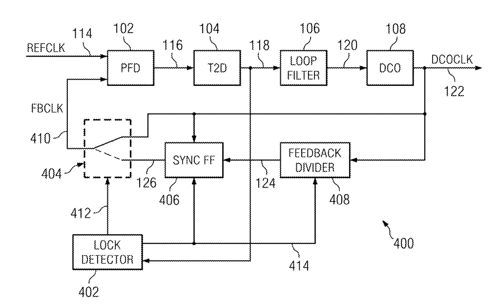
[0047]In accordance with an aspect of the present invention, a DPLL circuit initially functions like a conventional DPLL circuit by correcting the phase error between a reference clock signal and a feedback clock signal until both clock signals are aligned and the DPLL is locked. At that point, under certain conditions, in accordance with aspects of the present invention, the phase error can be derived from a phase comparison between an edge in the reference clock signal and the next closest edge in the oscillator clock signal rather than an edge in the feedback clock signal. In short, the feedback divider and the sync FF are bypassed, whereas the PFD compares the reference clock signal with the oscillator clock signal.

[0048]Aspects of the present invention may provide two distinct advantages over conventional DPLL circuits. First, if the phase jitter of DPLL is sufficiently small (which it is in many applications) the feedback divider can be disabled once initial frequency lock is ...


PUM


Abstract

A digital phase lock loop circuit, where under certain conditions the phase error is derived from phase comparison between a reference clock edge and the next oscillator clock edge rather than a feedback clock edge. This technique can be used to significantly reduce digital phase lock loop circuit power by disabling feedback divider and sync FF once initial frequency lock is established, provided phase jitter of digital phase lock loop circuit is low enough so that there is no cycle slip. This technique can also be used to multiply the effective reference clock frequency of digital phase lock loop circuits to increases the loop bandwidth, thus reducing the phase noise. Both the applications of this technique can be combined in some circuits.

Description

BACKGROUND[0001]Phase locked loop (PLL) circuits are widely known and used in computers, radios, telecommunications and many other electronic applications. One of the common uses of a PLL is to synthesize new frequencies ranging from a fraction of Hertz (Hz) up to many gigahertz (GHz), which are a multiple of a reference frequency and are as stable as reference frequency. Typical analog PLLs include a phase and frequency detector (PFD), a charge pump, a loop filter, a current controlled or voltage controlled oscillator (VCO) and a feedback path with a divider. A PLL uses negative feedback to control the output frequency of the oscillator until it matches with the reference signal in both frequency and phase. A fully digital PLL uses a digitally controlled oscillator (DCO), which is more robust and flexible than a conventional VCO. Digital PLLs are easy to design and less sensitive to voltage noise as compared to analog PLLs.[0002]FIG. 1 illustrates a prior art digital phase lock loo...

Claims


Application Information

Patent Timeline
Patent Type & Authority Applications(United States)
IPC IPC(8): H03L7/06
CPCH03L7/0802H03L7/104H03L7/095
Inventor NAGARAJ, KRISHNASAWAMY
Owner TEXAS INSTR INC
Why Eureka
Try Eureka