Radar system and antenna with delay lines and method thereof

a technology of delay lines and antennas, applied in direction finders, instruments, antennas, etc., can solve the problems of frequency scanning antennas, large power consumption, and high cost of phased array antennas, and achieve low power consumption, good range and angular resolution, and low cost

Inactive Publication Date: 2011-11-10
ARMY US SEC THE THE
View PDF41 Cites 42 Cited by
  • Summary
  • Abstract
  • Description
  • Claims
  • Application Information

AI Technical Summary

Benefits of technology

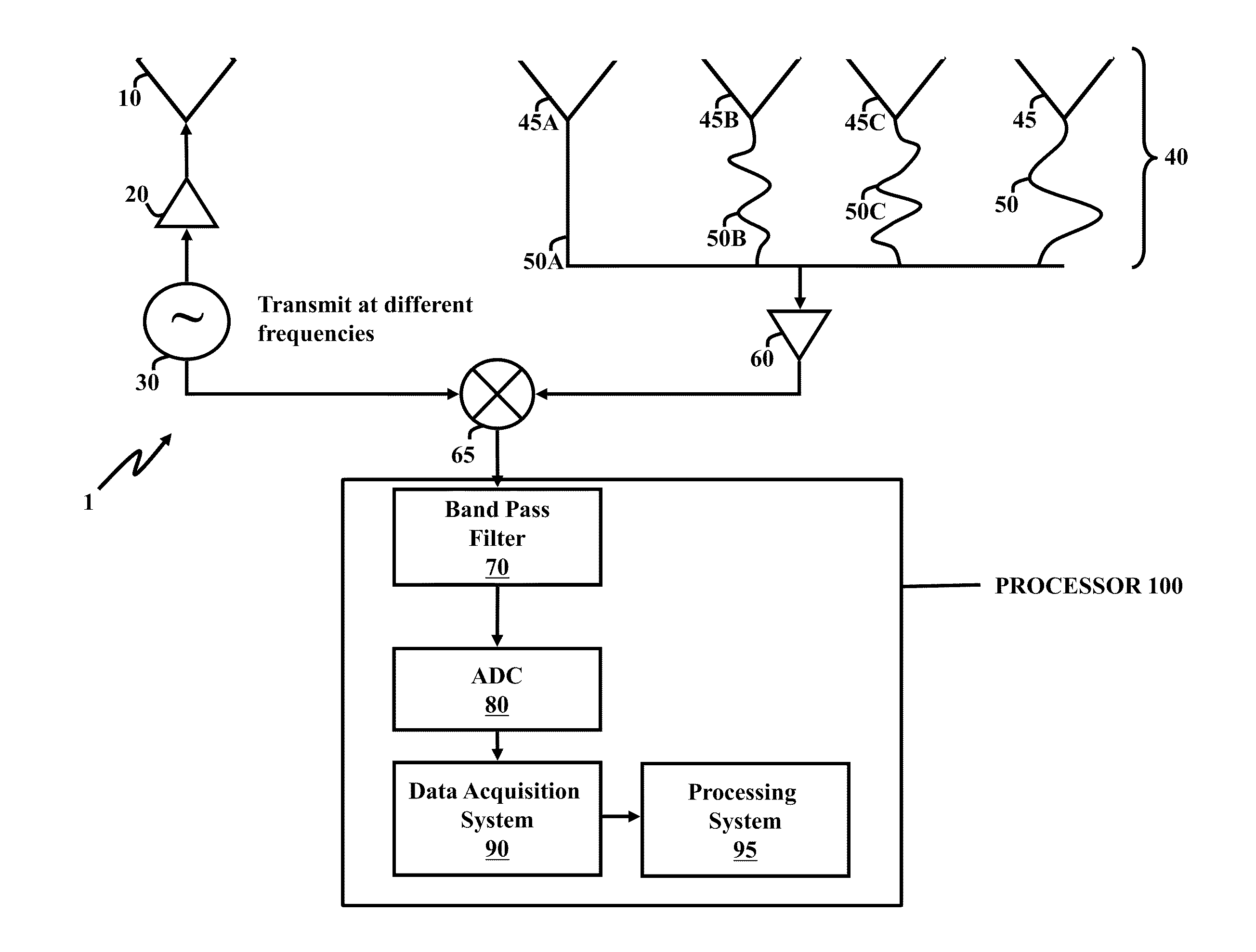
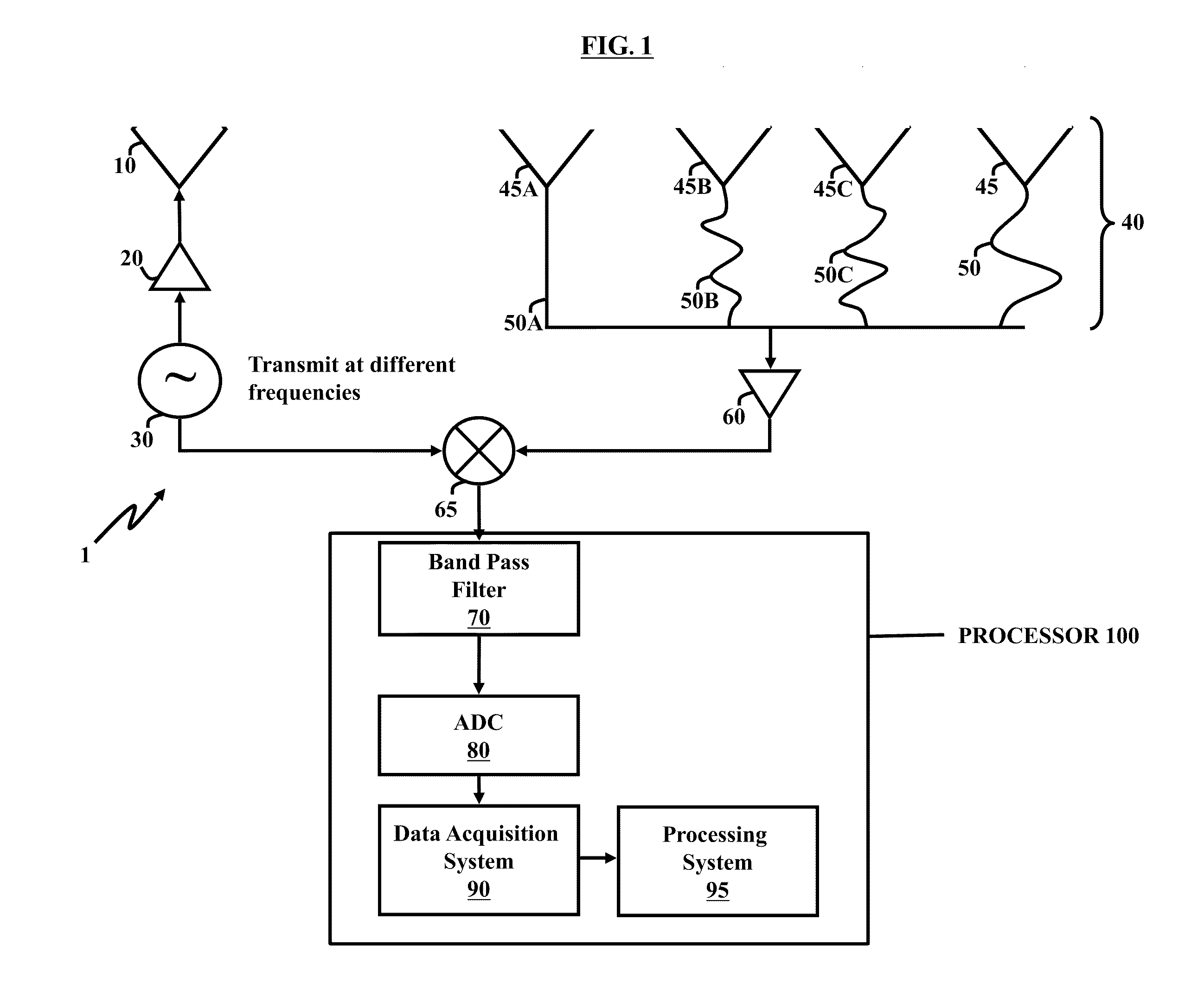
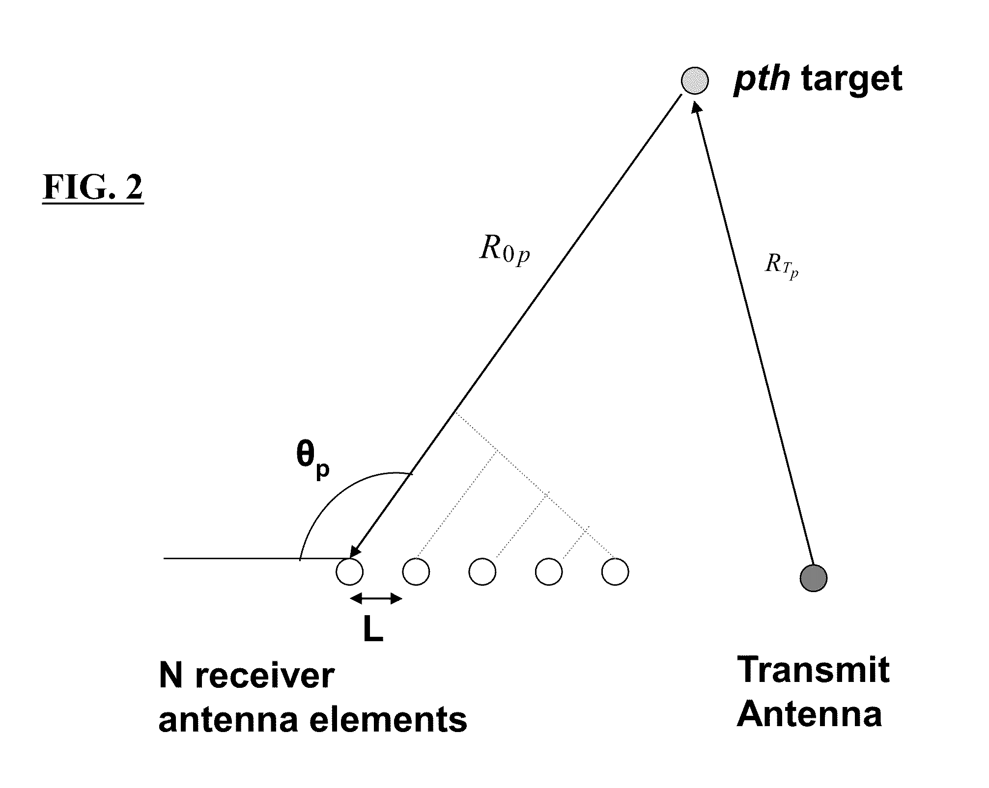
[0005]A preferred embodiment of the present invention provides a radar system with both good range and angular resolution at low cost and low power while having Electronically Scanning Array (ESA) capability without requiring elaborate phase shifters or other high cost precision active elements. A preferred embodiment is a radar system architecture comprising a plurality of receiving frequency scanning antenna elements operatively connected to delay lines whose lengths are somewhat randomly selected. The inputted (received) signal data is processed using digital signal processing algorithms. This architecture uses temporal diversity rather than spatial diversity to reduce the cost and improve the performance on the system.
[0007]A preferred embodiment architecture is based upon a 1-D linear array feed with predetermined fixed length lines (producing phase shifts; preferably selected with uniform distribution). The major advantages of a preferred embodiment architecture are a simple radar RF design, an antenna with no active elements, and a data acquisition system may be comprised of a single analog-to-digital converter (ADC). Previously, disadvantages associated with systems of this nature included the drawbacks of more complicated signal processing, reduction of the effective signal processing gain associated with the antenna system relative to a similar sized antenna, and increased potential ambiguities associated with target localization.
[0013]In a preferred embodiment, at least one processor or processing system may estimate angle, range, and velocity of the targets. The angle of the targets may be estimated by a matched filter and / or minimizing a weighted square error. Furthermore, at least one processor or processing system may estimate at least one of a velocity and a position of the detected targets. In addition, at least one processor or processing system may calculate a statistical optimization to determine at least one of a velocity and a position of a target, and the statistical optimization may be used to calculate a minimum value to a cost function formulation. Optionally, at least one processor or processing system may comprise a digital signal processor.
[0014]Another embodiment comprises an antenna array fed with randomly selected delay lines, comprising a plurality of antenna elements; a plurality of delay lines which may be of random length, each operatively connected to an antenna element; a data acquisition system coupled to the plurality of delay lines comprising an analog-to-digital converter; and a digital signal processor processing the electromagnetic wave data; and a processing system coupled to the data acquisition system, wherein the processing system detects the target and outputs location information of the target. The plurality of antenna elements may comprise a linear array or be positioned in a nonplanar configuration. Moreover, there may be non-linear (or different) spacing between the plurality of antenna elements. Additionally, at least one processor or e processing system may estimate an angle of the target by at least one of a matched filter and minimizing a weighted square error. In addition, at least one processor or processing system may estimate at least one of a velocity and a position of the target. Additionally, the analog-to-digital converter of the data acquisition system may comprise a single slow-speed analog-to-digital converter.

Problems solved by technology

Phased array antennas can be expensive and consume large amounts of power.
In systems using frequency scanning antennas, there is a trade-off between generally good angular resolution in exchange for poor range resolution.
Frequency scanning antennas, however, do not typically support 2-D scanning and high range resolution system requirements.
Consequently, radars using frequency scanning antennas have poor range resolution but good angular resolution.
Previously, disadvantages associated with systems of this nature included the drawbacks of more complicated signal processing, reduction of the effective signal processing gain associated with the antenna system relative to a similar sized antenna, and increased potential ambiguities associated with target localization.

Method used


Image

  • Radar system and antenna with delay lines and method thereof
  • Radar system and antenna with delay lines and method thereof
  • Radar system and antenna with delay lines and method thereof

Examples


Embodiment Construction

[0036]The embodiments of the invention and the various features and advantageous details thereof are explained more fully with reference to the non-limiting embodiments that are illustrated in the accompanying drawings and detailed in the following description. It should be noted that the features illustrated in the drawings are not necessarily drawn to scale. Descriptions of well-known components and processing techniques are omitted so as to not unnecessarily obscure the embodiments of the invention. The examples used herein are intended merely to facilitate an understanding of ways in which the embodiments of the invention may be practiced and to further enable those of skill in the art to practice the embodiments of the invention. Accordingly, the examples should not be construed as limiting the scope of the embodiments of the invention. Rather, these embodiments are provided so that this disclosure will be thorough and complete, and will fully convey the scope of the invention ...


PUM


Abstract

A radar system, apparatus, and method includes at least one radar transmitter for transmitting an electromagnetic waveform; a receiving antenna comprising a plurality of receiving antenna elements and delay lines, each of the plurality of receiving antenna elements receiving the return signal operatively associated with a predetermined delay line; each delay line having a delay length which produces a different phase delay in the return signal; the different phase delays producing substantially different antenna patterns for the received signal at a given frequency; at least one processor operatively connected to receive data from the plurality of delay lines; the at least one processor operating to analyze the substantially different beam patterns for a given frequency; whereby the processing of the data produces results indicating the presence and location of a target.

Description

GOVERNMENT INTEREST[0001]The embodiments herein may be manufactured, used, and / or licensed by or for the United States Government without the payment of royalties thereon.BACKGROUND OF THE INVENTION[0002]Moving target indicator radars have been used to detect and track targets since World War II. In searching for targets, a narrow beam is typically scanned through a large area of interest. Radar searches in years after WWII were mechanically performed by rotating an antenna on a gimbal. For more recently developed systems, the beam is scanned electronically with a phased array antenna using switches, ferroelectric, or other active devices. Phased array antennas can be expensive and consume large amounts of power. Another less expensive approach for scanning a radar beam is to use a frequency scanning antenna. In systems using frequency scanning antennas, there is a trade-off between generally good angular resolution in exchange for poor range resolution. Frequency scanning antennas,...

Claims


Application Information

Patent Timeline
Patent Type & Authority Applications(United States)
IPC IPC(8): G01S13/42H01Q3/22
CPCG01S3/46G01S2013/0263G01S13/42G01S7/03
Inventor GOLDMAN, GEOFFREY HOWARD
Owner ARMY US SEC THE THE
Why Eureka
Try Eureka