
Apparatus and associated method for providing a frequency configurable antenna employing a photonic crystal

a technology of photonic crystal and antenna, which is applied in the direction of antennas, antenna details, electrical apparatus, etc., can solve the problems of bulky and complicated multiband or frequency reconfigurable antennas, small devices with limited space, and undesirable to employ a plurality of individual antennas, etc., to achieve less complex management, less power consumption, and more economical

Active Publication Date: 2011-11-10
THE BOEING CO
View PDF3 Cites 12 Cited by
  • Summary
  • Abstract
  • Description
  • Claims
  • Application Information

AI Technical Summary

Benefits of technology

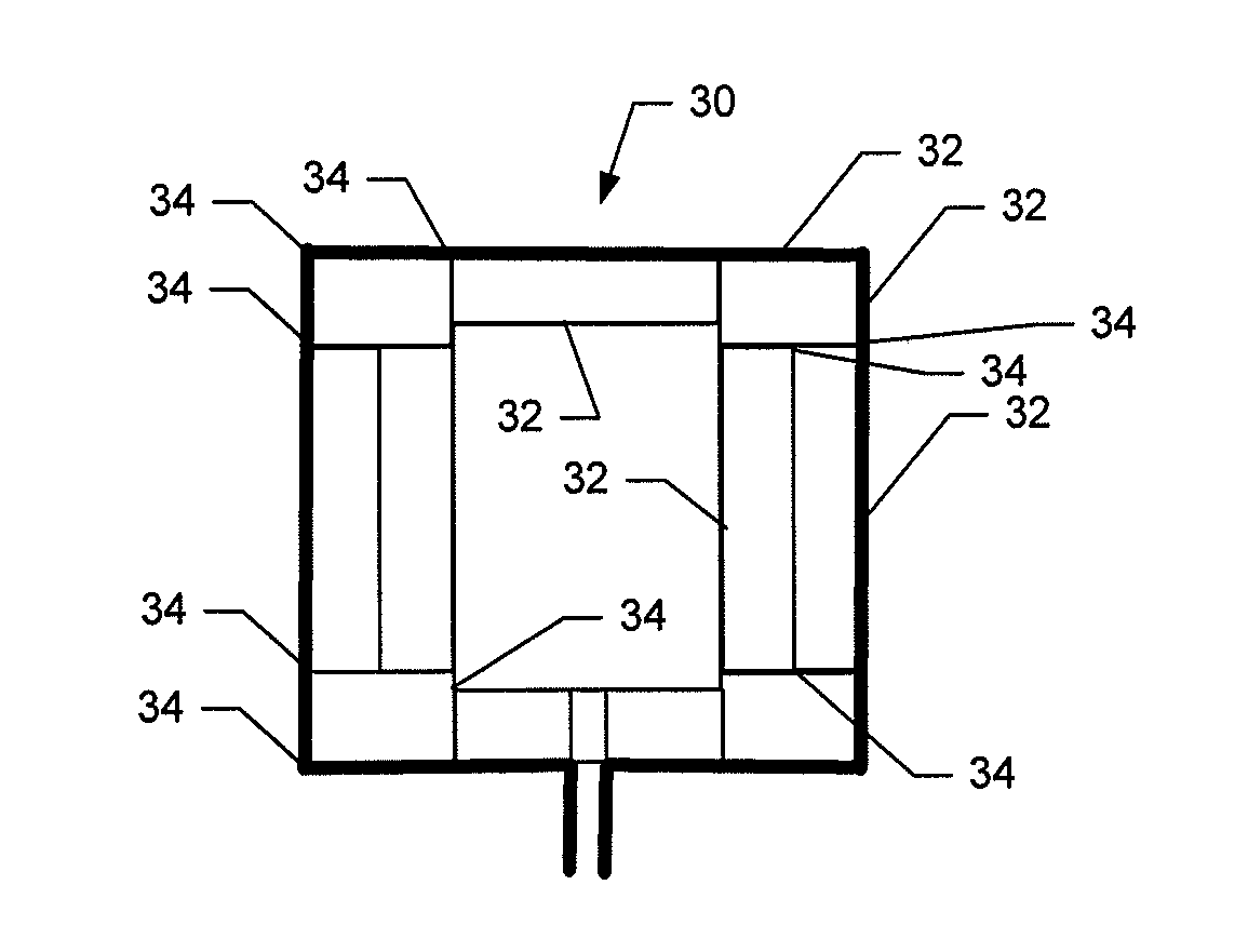
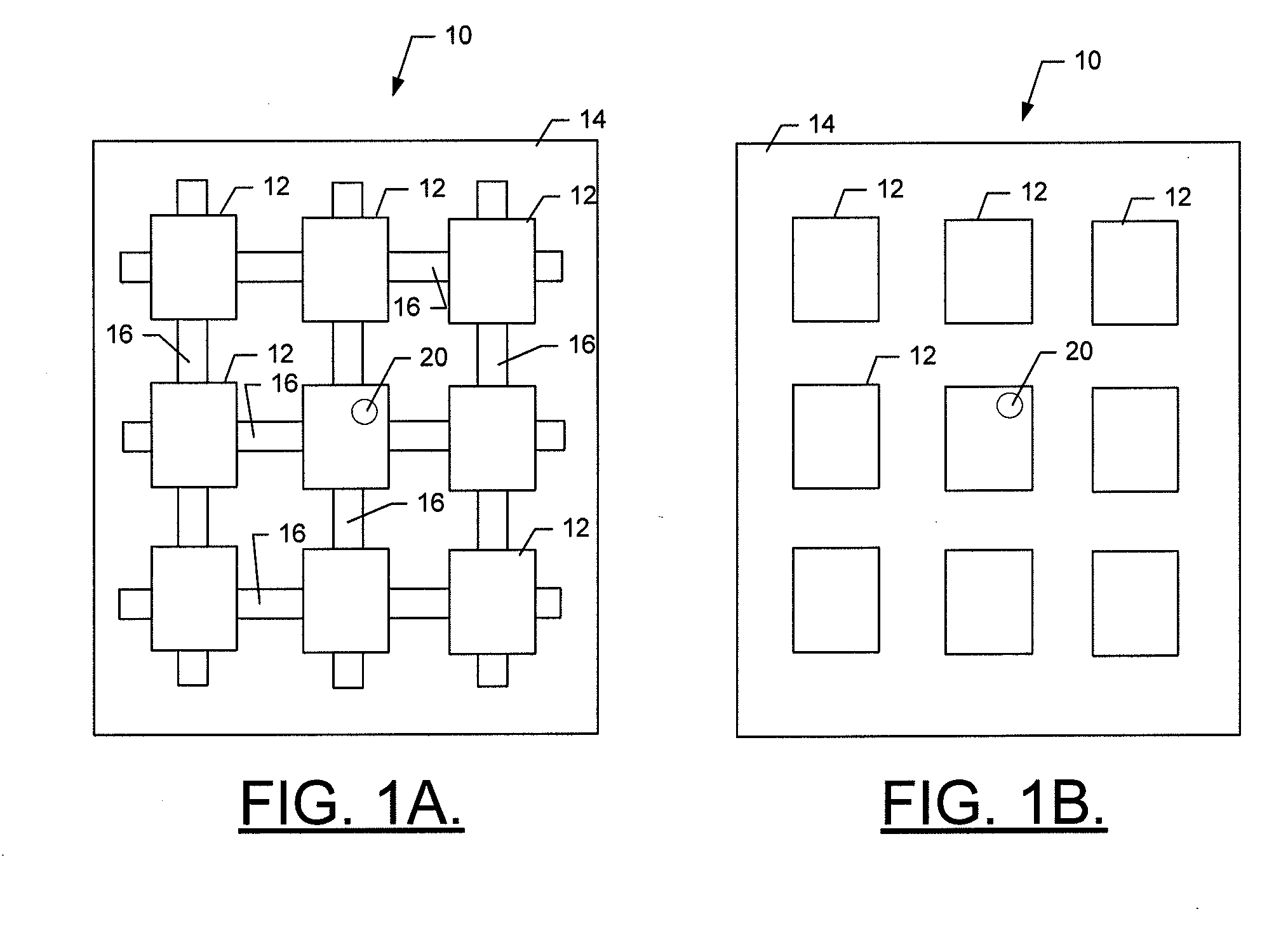
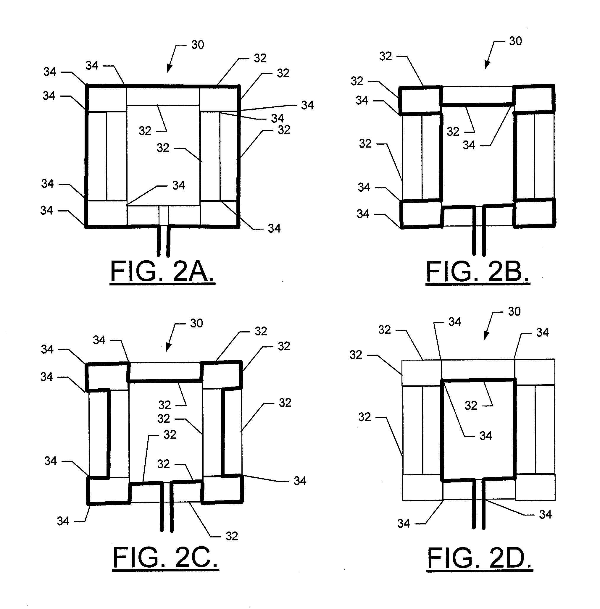
[0005]Some embodiments of the present disclosure may provide a frequency reconfigurable antenna that employs multiple elements and a photonic crystal as a switching device positioned between antenna elements. The photonic crystal may have electrically alterable states that can either deflect or pass electromagnetic radiation to thereby render the antenna element isolated or included to provide a frequency reconfigurable antenna. In some examples, a frequency configurable antenna with photonic crystals may be more economical, may consume less power and / or may require less complex management than at least some other types of frequency configurable antennas. Moreover, the frequency configurable antenna with photonic crystals may be incorporated in devices having a relatively small form factor, thereby increasing the variety of devices that may be serviced by the photonic crystal apparatuses according to embodiments of the present disclosure.

Problems solved by technology

Many of these smaller devices have limited space and parameters such as cost, space and weight considerations may be influential design factors.
Therefore, it may be undesirable to employ a plurality of individual antennas, or bulky and complicated multiband or frequency reconfigurable antennas.

Method used


Image

  • Apparatus and associated method for providing a frequency configurable antenna employing a photonic crystal
  • Apparatus and associated method for providing a frequency configurable antenna employing a photonic crystal
  • Apparatus and associated method for providing a frequency configurable antenna employing a photonic crystal

Examples


Embodiment Construction

[0014]The present disclosure now will be described more fully hereinafter with reference to the accompanying drawings, in which some, but not all embodiments are shown. Indeed, this disclosure may be embodied in many different forms and should not be construed as limited to the embodiments set forth herein; rather, these embodiments are provided so that this disclosure will satisfy applicable legal requirements. Like numbers refer to like elements throughout.

[0015]As discussed above, multiradio platforms may employ multiple individual antennas, multiband antennas or frequency reconfigurable antennas. Conventional embodiments of each of the antenna configurations listed above may typically have corresponding advantages and disadvantages. For example, typical single-band, dedicated antennas have superior performance attributes, but often occupy too much space (particularly for mobile or space critical platforms). Multiband antennas, which may address several bands or services simultan...


PUM


Abstract

A frequency reconfigurable antenna may include at least two antenna segments and a photonic crystal positioned between the at least two antenna segments. The photonic crystal may selectably electrically connect or isolate the at least two antenna segments with respect to each other based on a conductive state of the photonic crystal.

Description

TECHNOLOGICAL FIELD[0001]Embodiments of the present disclosure relate generally to methods and apparatus controllably configuring an antenna to receive and / or transmit electromagnetic signals and, more particularly, to methods and apparatus for employing a photonic crystal for controllably configuring an antenna to receive and / or transmit electromagnetic signals of selectable frequencies.BACKGROUND[0002]Modern aircraft include a number of different communications systems. These systems may include, for example, public cabin Wi-Fi connectivity systems, crew information systems, wireless passenger service units, wireless passenger control units, wireless emergency lighting systems, commercial mobile radio services, and the like. Some wireless systems may operate using a single frequency. However, other wireless communication systems may operate over multiple frequencies. To support operations over multiple frequencies and perhaps also to support multiple different systems, aircraft an...

Claims


Application Information

Patent Timeline
Patent Type & Authority Applications(United States)
IPC IPC(8): H01Q1/00H01Q9/04
CPCH01Q21/065H01Q9/0442
Inventor WILKINS, DONALD FRANK
Owner THE BOEING CO
Learn More